Compression vs Injection Molding: Key Differences, Costs, and When to Choose Each
Compression vs injection molding determines your production economics, part quality, and tooling ROI for the next 5–10 years.
Injection molding forces molten thermoplastic resins into closed molds at high clamping force, optimized for mass production of complex, high-precision geometries.
Compression molding utilizes thermosetting polymers under sustained vertical pressure in open cavities, ideal for high-strength, large-scale composite parts.
Select based on material chemistry, cycle time targets, and annual volume thresholds, not surface-level price estimates.
Contents
- 1 What Decision Are You Actually Making Between Compression and Injection Molding?
- 2 Process Fundamentals: How Compression Molding and Injection Molding Actually Work
- 3 Material Compatibility and Performance Outcomes
- 4 Tooling, Cycle Time, and Manufacturing Economics
- 5 Part Design Flexibility and Geometric Constraints
- 6 Quality, Strength, and Structural Performance
- 7 Typical Applications and Industry Use Cases
- 8 Compression Molding vs Injection Molding: Side-by-Side Comparison Table
- 9 Which Process Should You Choose for Your Project?
- 10 Final Recommendation Based on Cost, Performance, and Scale
- 11 FAQs
- 11.1 Is compression molding cheaper than injection molding?
- 11.2 Why choose compression molding over injection molding for composites?
- 11.3 Can you use thermoplastics in compression molding?
- 11.4 What are the typical tolerances for injection vs. compression molding?
- 11.5 Which process has a better energy efficiency rating in 2026?
What Decision Are You Actually Making Between Compression and Injection Molding?
Production volume vs part complexity trade-off
Compression molding delivers cost efficiency at volumes below 10,000 units annually, particularly for large-format parts with simple geometries.
Injection molding requires $50K–$500K tooling investment but achieves the lowest per-part cost above 50,000 units/year through automated cycles and minimal labor.
The break-even point sits at 15,000–25,000 parts, depending on part size, material selection, and secondary operations.
Material behavior under pressure and heat
Injection molding generates shear heat as thermoplastic resins flow through runners and gates at 180–300°C, enabling complex cavitation but risking molecular degradation.
Compression molding applies static pressure (1,000–3,000 psi) to thermosetting compounds like BMC or SMC, curing through sustained heat transfer without shear-induced stress.
This difference dictates surface finish quality, internal void formation, and dimensional tolerances across production runs.
Cost drivers that influence long-term ROI
- Tooling maintenance: Injection molds require precision H13 tool steel with annual maintenance costs of 3–7% of initial investment; compression tooling uses simpler designs with half the upkeep frequency.
- Energy consumption per kg: Injection molding consumes 1.2–2.0 kWh/kg due to barrel heating and hydraulic clamping; compression uses 0.6–1.0 kWh/kg through platen heating alone.
- Secondary finishing costs: Compression molding generates flash requiring trimming operations at $0.50–$2.00/part; injection molding delivers near-net-shape parts with minimal post-processing below $0.10/part.
Process Fundamentals: How Compression Molding and Injection Molding Actually Work
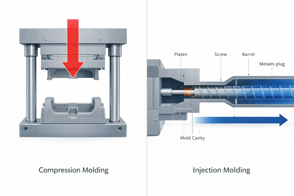
Compression molding workflow (charge, pressure, cure)
- Charge placement: Operators position pre-weighed bulk molding compound (BMC) or sheet molding compound directly into the open heated cavity at 140–180°C. Material distribution determines final part density and fiber orientation in composite structures.
- Vertical compression: Hydraulic presses apply 1,000–3,000 psi clamping force as platens close, forcing material outward to cavity edges. Excess resin creates flash at parting lines requiring secondary trimming operations.
- In-mold curing: Thermosetting polymers crosslink under sustained heat and pressure for 60–300 seconds depending on part thickness. Parts de-mold only after complete polymerization, limiting cycle times to 2–8 minutes.
Injection molding workflow (plasticization, injection, cooling)
- Screw plasticization: Reciprocating screws rotate at 60–120 RPM, generating shear heat that melts thermoplastic resins to 180–300°C in heated barrels. Back pressure controls melt homogeneity and minimizes air entrapment during shot preparation.
- High-velocity injection: Hydraulic or electric systems inject molten polymer at 50–200 mm/s through runners, gates, and into closed cavities under 10,000–25,000 psi. Mold flow analysis predicts fill patterns to prevent short shots and weld lines.
- Rapid cooling/ejection: Conformal cooling channels circulate water at 10–40°C, solidifying parts in 10–60 seconds. Ejector pins release parts automatically, enabling cycle times of 15–90 seconds for high-volume production.
Tooling architecture differences that affect scalability
Injection molds use H13 tool steel with complex geometries including conformal cooling channels, slide actions, and multi-cavity layouts that cost $50K–$500K but enable million-unit runs.
Compression tooling employs simpler matched-die designs with basic platen heating and minimal moving components, reducing initial investment to $10K–$80K but limiting automation potential. Injection molds require precision maintenance every 50,000–100,000 cycles; compression tools operate 100,000+ cycles with basic cleaning protocols.
This architecture gap determines whether you optimize for per-part cost at scale or capital preservation at lower volumes.
Material Compatibility and Performance Outcomes
Thermosets vs thermoplastics suitability
Thermosetting polymers (phenolics, epoxies, polyester resins) chemically crosslink during compression molding without exposure to mechanical shear, preserving molecular chain integrity and achieving superior heat resistance up to 300°C. Injection molding degrades thermosets through screw rotation and barrel residence times, making the process incompatible.
Thermoplastic resins (ABS plastic, Nylon) require the reversible melt-solidify cycle that injection molding provides, flowing through runners at 180–300°C before rapid cooling. Compression molding cannot process thermoplastics effectively due to insufficient shear heat generation and prolonged cure times.
Select compression for thermoset chemistry requiring zero shear exposure; choose injection for high-volume thermoplastic parts with complex geometries.
Fiber reinforcement behavior (SMC, BMC, glass-filled resins)
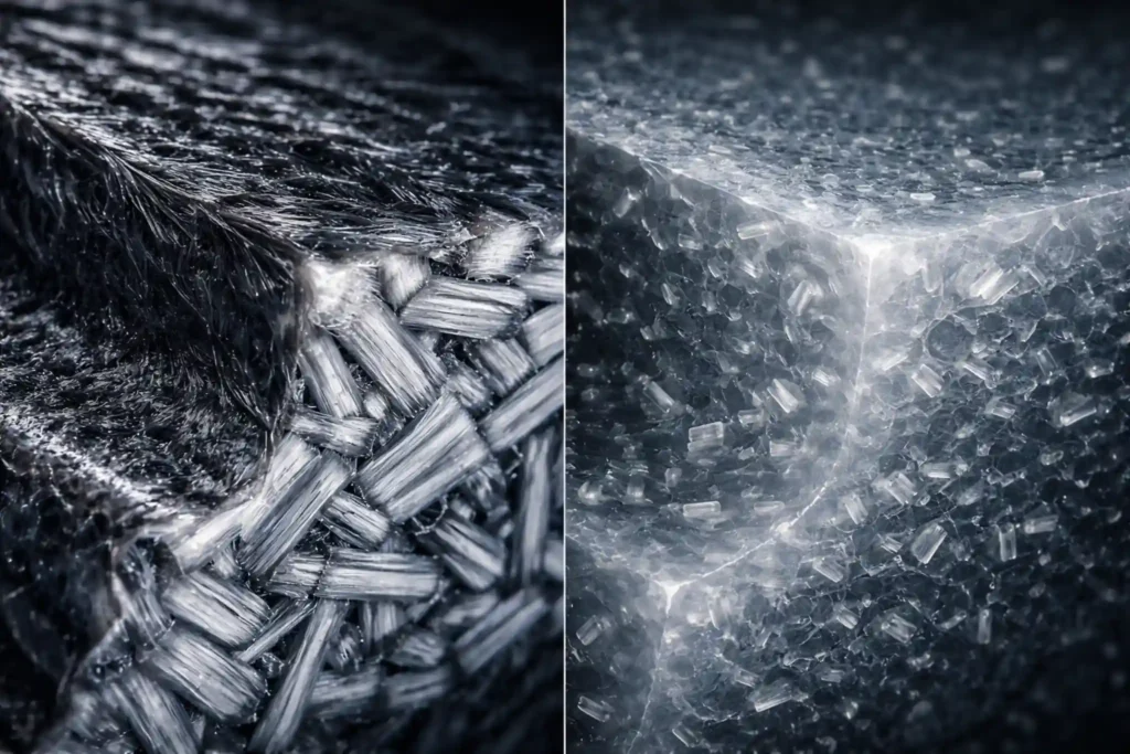
Compression molding preserves fiber lengths of 12–50mm in sheet molding compound (SMC) and bulk molding compound (BMC), maintaining directional strength properties critical for structural automotive and electrical components. Static pressure distributes fibers without the mechanical breakage caused by injection screw rotation and high-velocity gate flow.
Injection-molded glass-filled resins experience fiber attrition to 0.2–3mm lengths during plasticization, reducing tensile strength by 20–40% compared to compression-molded equivalents.
Impact strength advantage: Compression-molded SMC delivers 15–25% higher Izod values than injection-molded glass-filled thermoplastics at equivalent fiber loading percentages. This performance gap determines material selection for Class 1 electrical enclosures, under-hood automotive parts, and structural aerospace components where impact resistance justifies longer cycle times.
Dimensional stability and surface finish limits
Injection molding achieves shrinkage rates of 0.3–0.8% for unfilled thermoplastics through precise cavity pressure control and rapid cooling, enabling ±0.05mm tolerances on small parts.
Compression molding exhibits 1.0–3.0% shrinkage in thermosets due to volatile release during cure and thermal contraction variability.
Class A surface finishes with mirror-polish quality emerge naturally from injection’s high cavity pressures and controlled mold temperatures. Compression molding requires secondary finishing operations to eliminate flash lines and achieve cosmetic-grade surfaces, adding $0.50–$2.00/part in post-processing costs for visible applications.
Tooling, Cycle Time, and Manufacturing Economics
Mold cost comparison and tooling lifespan
Injection molding tooling ranges from $30K for single-cavity prototypes to $500K+ for multi-cavity production molds using precision-machined H13 tool steel with conformal cooling channels and automated ejection systems.
Compression molding tooling costs $5K–$15K for simple matched dies and $25K–$80K for complex multi-cavity configurations, requiring only basic platen heating without intricate cooling networks. Injection molds deliver 500,000–2,000,000 cycles before major refurbishment; compression tools achieve 100,000–500,000 cycles with minimal maintenance beyond cleaning and surface polishing.
This 10:1 initial cost differential makes compression viable for pilot production and low-volume manufacturing where injection’s CAPEX cannot be amortized across sufficient unit volumes.
Cycle time differences and throughput impact
| Process | Typical Cycle Time |
| Injection Molding | 15–90 seconds (small to medium thermoplastic parts with automated ejection) |
| Compression Molding | 2–8 minutes (thermoset cure time drives cycle; manual charge placement adds 20–40 seconds) |
Injection molding achieves 40–240 parts/hour per cavity through rapid cooling and automated part handling.
Compression molding produces 8–30 parts/hour due to in-mold curing requirements and manual material loading.
This 5–10x throughput advantage positions injection as the only viable process above 50,000 annual units, where labor costs and floor space utilization justify high tooling investments.
Scrap rate, rework, and material utilization
Compression molding generates 5–15% material waste through flash formation at parting lines, requiring trimming operations that add $0.50–$2.00/part in labor and disposal costs.
Injection molding produces 2–8% scrap from runners, sprues, and startup purge, but thermoplastic waste can be reground and reused at 15–25% blend ratios without significant property degradation. Thermoset flash from compression cannot be recycled, creating permanent material loss.
Net material utilization favors injection by 10–20 percentage points when regrind systems are implemented, directly impacting cost per kilogram in high-volume production environments.
Part Design Flexibility and Geometric Constraints
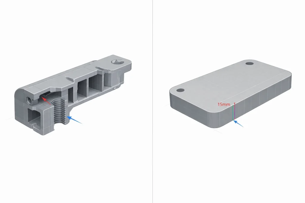
Wall thickness control and part uniformity
Injection molding requires uniform wall thickness of 1.5–4.0mm to prevent sink marks, voids, and differential cooling rates that cause warpage in thick sections. Parts exceeding 6mm wall thickness experience surface depression as internal material shrinks faster than outer layers.
Compression molding handles thick-walled sections of 6–25mm without sink marks due to static pressure distribution and controlled cure rates throughout the cross-section.
Structural components requiring high rigidity, electrical enclosures, equipment housings, automotive brackets favor compression when wall thickness exceeds 8mm, where injection’s cooling limitations create quality defects and extended cycle times that eliminate cost advantages.
Undercuts, ribs, bosses, and complex features
- Undercuts and internal threads: Injection molds incorporate sliding cores, lifters, and unscrewing mechanisms to form complex internal geometries automatically; compression molding requires manual inserts or post-machining for any feature not parallel to the press direction, adding $1.50–$5.00/part in secondary operations.
- Ribs and stiffening features: Injection molding creates ribs as thin as 0.6mm with precise height-to-thickness ratios through high-pressure cavity filling; compression struggles with rib features below 3mm thickness due to incomplete material flow in thin sections under static pressure.
- Bosses and mounting posts: Injection processes form integral bosses with molded-in inserts in a single cycle; compression molding achieves bosses but requires generous draft angles (3–7°) and cannot economically incorporate threaded inserts during molding, necessitating ultrasonic or heat-staking insertion post-cure.
Tolerance expectations for each process
Injection molding delivers ±0.05mm tolerances on critical dimensions for small parts under 100mm, tightening to ±0.02mm with scientific molding protocols and process monitoring.
Compression molding achieves ±0.2–0.5mm on primary dimensions due to material flow variability, flash formation, and thermal expansion differences during cure cycles.
Parts requiring precise mating surfaces, snap-fit assemblies, or optical clarity demand injection’s dimensional control.
Select compression only when ±0.3mm tolerances satisfy functional requirements and cost considerations outweigh precision needs.
Quality, Strength, and Structural Performance
Fiber length retention and mechanical strength
Compression molding preserves 12–50mm fiber lengths in SMC and BMC formulations, creating quasi-isotropic mechanical properties with tensile strength varying only 10–15% across directional axes.
Injection molding reduces fibers to 0.2–3mm fragments through screw shear and gate velocity, producing 30–50% strength differential between flow direction and transverse orientation due to pronounced mechanical anisotropy. This directional dependency requires mold flow analysis to orient weld lines and fiber paths away from high-stress regions.
Load-bearing components in aerospace, heavy equipment, and electrical infrastructure favor compression’s balanced strength profiles, eliminating failure risks from unexpected load angles. Injection suits applications where engineers control stress orientation through rib placement and part geometry optimization.
Void content, porosity, and defect risks
Injection molding traps air during high-velocity filling (50–200 mm/s) creating microvoids at weld lines where flow fronts converge and gas pockets in thick sections lacking adequate venting. Void content of 0.5–2.0% reduces tensile strength by 8–15% and initiates crack propagation under cyclic loading.
Compression molding eliminates gas entrapment through slow material displacement and vacuum-assisted variants that evacuate air before final pressure application, achieving void content below 0.3%. Electrical enclosures and pressure vessels require compression’s superior consolidation to prevent dielectric breakdown and leak paths.
Injection compensates through strategic vent placement and gas-assist molding for critical applications, adding $15K–$40K to tooling costs.
Long-term fatigue and load-bearing behavior
Compression-molded thermosets exhibit fatigue life of 10^6–10^7 cycles at 50% ultimate tensile strength due to cross-linked polymer networks resistant to creep and stress relaxation.
Injection-molded thermoplastics demonstrate fatigue endurance of 10^4–10^6 cycles with 15–25% strength degradation over time from molecular chain slippage under sustained loads. Glass-filled nylon and polypropylene mitigate creep but cannot match thermoset dimensional stability at elevated temperatures.
Structural components with 10–20 year service lives under continuous mechanical stress, transformer housings, motor mounts, industrial valve bodies require compression molding’s long-term load retention to prevent catastrophic failure.
Typical Applications and Industry Use Cases
Automotive, electrical, and aerospace applications
- Automotive: Compression molding produces Class A body panels, under-hood components (valve covers, air intake manifolds), and structural battery enclosures requiring high heat resistance and impact strength. Injection molding creates interior trim, lens assemblies, fluid reservoirs, and complex connector housings demanding tight tolerances and high-volume throughput.
- Electrical: Compression molding delivers transformer housings, circuit breaker enclosures, and high-voltage insulators using arc-resistant thermosets with UL 94 V-0 ratings. Injection molding produces consumer electronics cases, LED light housings, and miniature switch components requiring cosmetic finishes and sub-millimeter features.
- Aerospace: Compression molding forms radomes, aircraft interior panels, and satellite structural components preserving fiber strength and minimizing void content below 0.3%. Injection molding supplies galley components, seat frame brackets, and HVAC ducting where weight reduction through part consolidation justifies higher material costs.
High-strength structural parts vs high-detail components
Compression molding dominates applications requiring tensile strength above 150 MPa, operating temperatures exceeding 200°C, and wall thicknesses of 6–25mm, transformer housings, motor end bells, industrial equipment covers.
Injection molding serves parts demanding surface finish tolerances under ±0.05mm, features below 1mm thickness, and cosmetic Class A surfaces, medical device housings, consumer electronics, automotive interior components.
Engineers select compression when material performance and structural integrity drive specifications; choose injection when geometric complexity and production economics determine feasibility.
When OEMs deliberately avoid one process
Aerospace OEMs reject injection molding for large-format panels exceeding 0.5m² surface area due to residual stress accumulation from differential cooling rates and fiber orientation misalignment during high-velocity filling.
Boeing and Airbus suppliers specify compression molding for fuselage panels, wing components, and control surface skins to eliminate warpage risks and maintain dimensional stability across -55°C to +85°C operating ranges.
Automotive OEMs avoid compression molding for high-volume interior components (>100,000 units/year) where 2–8 minute cycle times create unacceptable labor costs and floor space requirements.
Tier 1 suppliers mandate injection molding for instrument panels, door handles, and climate control bezels to achieve 15–45 second cycles enabling just-in-time delivery to assembly lines.
Medical device manufacturers exclude compression molding from implantable components due to flash contamination risks and inability to validate sterile molding environments required by FDA 21 CFR Part 820 regulations.
Compression Molding vs Injection Molding: Side-by-Side Comparison Table
| Feature | Compression Molding | Injection Molding |
| Material Chemistry | Thermosets (SMC, BMC, Phenolic) | Thermoplastics (ABS, PC, Nylon) |
| Tooling Investment | Low ($10K–$80K) | High ($50K–$500K+) |
| Cycle Time | 2–8 Minutes | 15–90 Seconds |
| Annual Volume | <15,000 Units (Optimal) | >50,000 Units (Optimal) |
| Wall Thickness | 6mm–25mm (No Sink Marks) | 1.5mm–4mm (Requires Uniformity) |
| Tolerance Range | ±0.2mm to ±0.5mm | ±0.02mm to ±0.05mm |
Which Process Should You Choose for Your Project?
Low-volume, high-strength decision scenarios
Select compression molding when annual volumes remain below 15,000 units, part wall thickness exceeds 6mm, and applications demand thermoset heat resistance above 200°C or fiber-reinforced impact strength.
Prioritize compression for structural electrical enclosures, aerospace components, and industrial equipment housings where $5K–$25K tooling investment enables production starts within 6–10 weeks and material performance outweighs cycle time concerns.
Accept 2–8 minute cycles and $0.50–$2.00/part flash removal costs as necessary trade-offs for superior mechanical properties and capital preservation in pilot production or niche manufacturing programs.
High-volume, precision-driven production scenarios
Choose injection molding when annual volumes exceed 50,000 units, geometric complexity requires ribs below 1.5mm thickness, and ±0.05mm tolerances are non-negotiable for assembly or cosmetic requirements.
Deploy injection for consumer products, automotive interiors, and medical devices where $30K–$500K tooling costs amortize across sufficient production runs to achieve per-part costs below $0.50 through 15–90 second cycle times and automated handling systems.
Invest in mold flow analysis ($3K–$8K) and scientific molding protocols to eliminate defects during validation, ensuring first-article approval and preventing costly tool modifications after production launch.
Common selection mistakes engineers make
- Underestimating tooling lead times: Engineers allocate 8–12 weeks for injection mold fabrication but face 16–24 week realities for complex multi-cavity tools with slides and lifters, delaying product launches by 3–6 months and creating supply chain gaps that cost $50K–$200K in expedite fees or lost revenue opportunities.
- Overlooking secondary finishing costs: Teams budget for molding at $1.50/part but ignore $0.50–$2.00/part trimming, deburring, and painting operations required for compression-molded components, inflating actual production costs by 30–60% and eliminating anticipated profit margins on mid-volume programs.
- Ignoring material regrind economics: Purchasing evaluates virgin resin costs but fails to model 15–25% regrind integration available in injection molding, missing $0.15–$0.40/kg material savings that compound to $30K–$100K annually on high-volume thermoplastic programs running multiple shifts.
Final Recommendation Based on Cost, Performance, and Scale
When compression molding is the smarter long-term choice
- Choose compression for annual volumes below 15,000 units, parts requiring wall thickness above 6mm, and applications demanding thermoset thermal stability or fiber-reinforced structural performance.
- Prioritize compression when tooling budgets under $25K enable faster market entry and material properties justify 2–8 minute cycle times.
- Accept flash removal costs of $0.50–$2.00/part for aerospace components, electrical enclosures, and industrial housings where performance specifications eliminate injection as viable alternative.
When injection molding clearly outperforms
- Select injection for production exceeding 50,000 annual units, parts requiring ±0.05mm tolerances, and designs featuring ribs below 1.5mm or complex internal geometries impossible to achieve through compression.
- Deploy injection when 15–90 second cycle times and automated handling systems deliver per-part costs below $0.50, amortizing $30K–$500K tooling investment across sufficient volume.
- Choose injection for consumer products, automotive interiors, and medical devices prioritizing cosmetic Class A finishes and geometric precision.
FAQs
Is compression molding cheaper than injection molding?
Compression molding is generally 30%–70% cheaper for upfront tooling, with molds costing $5,000–$25,000 compared to injection molding’s $30,000–$500,000+.
However, injection molding becomes more cost-effective at volumes above 15,000–25,000 units due to faster cycle times (seconds vs. minutes) and lower per-part labor costs.
Why choose compression molding over injection molding for composites?
Compression molding is the preferred choice for fiber-reinforced composites (SMC/BMC) because it preserves fiber length (12mm–50mm).
Unlike injection molding, which shears and breaks fibers down to 0.2mm–3mm during the high-velocity injection process, compression uses static pressure that maintains the material’s structural integrity and impact strength.
Can you use thermoplastics in compression molding?
While technically possible, compression molding is rarely used for thermoplastics. The process lacks the shear heat and efficient cooling cycles required for thermoplastics to flow into complex shapes.
It is primarily optimized for thermosetting polymers (like epoxies and phenolics) that cure through sustained heat and pressure rather than a melt-freeze cycle.
What are the typical tolerances for injection vs. compression molding?
Injection molding offers superior precision with standard tolerances of ±0.05mm and can reach ±0.02mm with scientific molding protocols.
Compression molding is less precise, typically achieving tolerances between ±0.2mm and ±0.5mm due to material flow variability and the formation of flash at the parting line.
Which process has a better energy efficiency rating in 2026?
Compression molding is typically 25%–38% more energy-efficient (kWh/kg of resin) than injection molding. It operates at lower resin temperatures and lacks the high-power requirements of hydraulic screw-driven injection units and complex hot runner systems, making it a stronger choice for ESG-focused manufacturing in 2026.
Usama is the founder of PlasticSpec and a materials researcher specialising in engineering thermoplastics. He publishes machining parameters, material property data, and selection guides for Delrin, Nylon, PEEK, PTFE, UHMW, Polycarbonate, and ABS.