Machining UHMW: Tools, Speeds, Tolerances & Common Problems
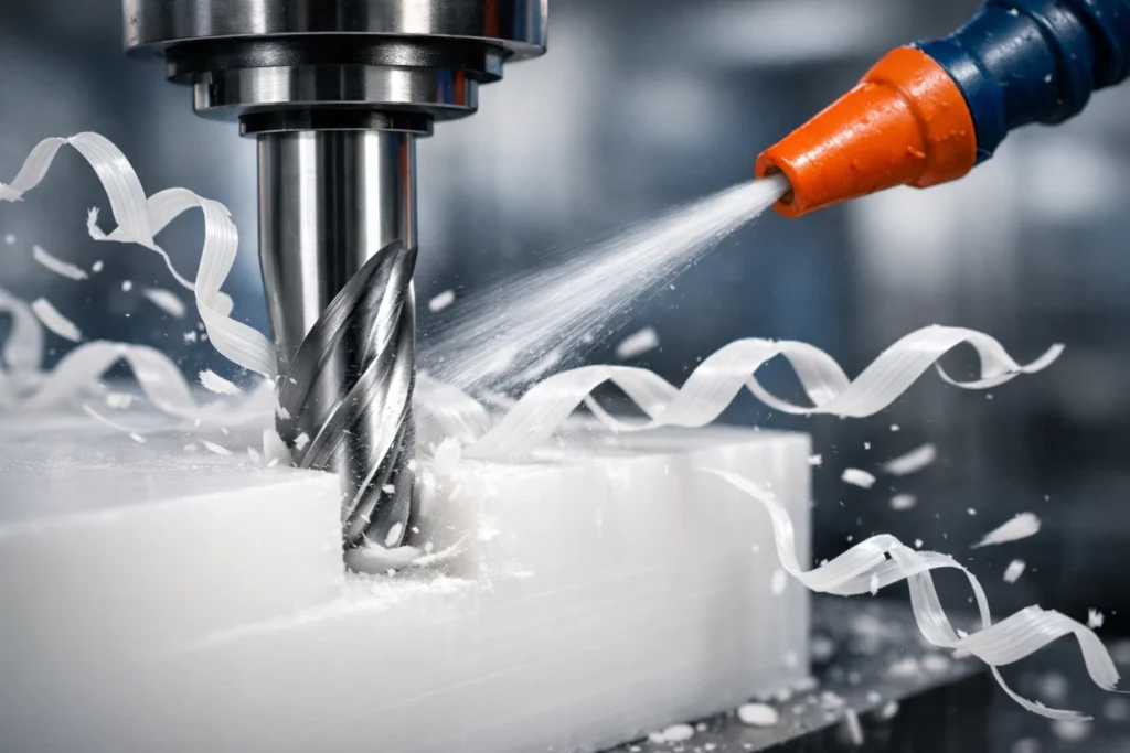
UHMW (Ultra-High Molecular Weight Polyethylene) is an engineering paradox: it is one of the most wear-resistant polymers available, yet it is notoriously difficult to machine to tight tolerances. Because its thermal expansion is 12x higher than steel and it possesses high elastic memory, standard machining approaches will cause melting, warping, and “rat-nesting” of chips.
To succeed, you must shift your mindset: UHMW behaves more like hard wax or cheese than metal. High spindle speeds are your enemy; sharp, high-positive rake angles are your primary solution.
Contents
- 1 Quick Machining Overview (Fast Reference Guide)
- 2 Why UHMW Is Challenging to Machine
- 3 UHMW vs. Delrin (Acetal): Which Should You Choose?
- 4 Recommended Cutting Tools for UHMW
- 5 Speeds and Feeds for Machining UHMW
- 6 Milling UHMW
- 7 Drilling and Tapping UHMW
- 8 Surface Finish & Deburring
- 9 Tolerances & Dimensional Stability
- 10 Coolant & Lubrication Recommendations
- 11 Common Machining Problems (And How to Fix Them)
- 12 Welding and Post-Machining Fabrication
- 13 Safety Considerations When Machining UHMW
- 14 When Not to Machine UHMW
- 15 Frequently Asked Questions
Quick Machining Overview (Fast Reference Guide)
| Operation | Tooling Type | Speed (SFM) | Feed (IPR/IPT) | Coolant |
| Milling | Single-Flute Carbide (Uncoated) | 600 – 900 | 0.010″ – 0.020″ | Air Blast / Flood |
| Turning | High-Positive Rake HSS/Carbide | 400 – 700 | 0.015″ – 0.025″ | Required |
| Drilling | Wide-Flute “Plastic” Drill Bits | 100 – 200 | 0.005″ – 0.015″ | Flood (Internal) |
| Tapping | Oversized (H5/H7) Taps | 30 – 50 | Pitch-Matched | Manual/Fluid |
Why UHMW Is Challenging to Machine
Extremely High Molecular Weight
UHMW’s long molecular chains make it incredibly tough and impact-resistant, but they also prevent the material from “chipping” cleanly. Instead of snapping, the material tears, leading to the characteristic “fuzz” or burrs on finished edges.
Low Melting Temperature
With a melting point of only 270°F (132°C), UHMW will begin to soften and “gall” (stick to the tool) long before you see smoke. Friction is the enemy. If your tool is dull or your feed rate is too slow, the material will rub, melt, and weld itself to your cutter.
High Thermal Expansion
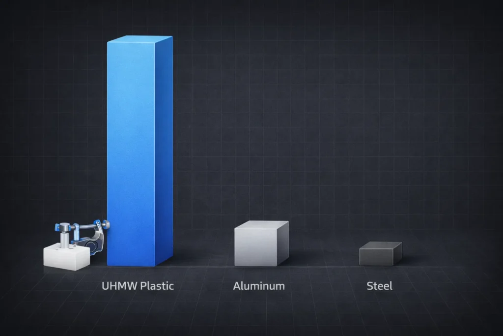
UHMW has a linear thermal expansion coefficient of approximately 1.1 x 10⁻⁴ in/in/°F.
- The Risk: A 10-inch part will expand 0.011″ for every 10°F increase in temperature.
- The Result: Parts measured “in-spec” while warm on the machine will shrink and become undersized once they reach room temperature.
Material “Push-Away” During Cutting
Due to its high elasticity, UHMW acts like a spring. When a cutting tool exerts pressure, the material compresses and “ducks” under the edge. Once the tool passes, the material springs back, resulting in high spots and inconsistent diameters.
UHMW vs. Delrin (Acetal): Which Should You Choose?
Choosing between UHMW and Delrin (Acetal) is a trade-off between extreme durability and precision engineering. While both are high-performance thermoplastics, they serve fundamentally different mechanical purposes.
- Choose UHMW when your primary goal is impact absorption, extreme wear resistance, or a low coefficient of friction in non-precision environments (e.g., chute liners, wear strips).
- Choose Delrin when you require tight tolerances (<.002″), high stiffness, or dimensional stability in mechanical assemblies (e.g., gears, precision bushings).
Comparison Table: Machinability vs. Performance
| Feature | UHMW (Polyethylene) | Delrin (Acetal Homopolymer) | Engineering Impact |
| Machinability | Difficult (Gums/Melts) | Excellent (Crisp Chips) | Delrin reduces cycle time and tool wear. |
| Tolerance Ability | Low (±.005″ to .010″) | High (±.001″ to .002″) | UHMW “creeps” and expands. |
| Tensile Strength | 3,100 PSI (Softer) | 10,000 PSI (Rigid) | Delrin handles 3x more structural load. |
| Impact Strength | Highest (No Cracking) | Moderate (Can Fracture) | UHMW is nearly indestructible under shock. |
| Friction (CoF) | 0.10 – 0.20 (Slippery) | 0.20 – 0.30 (Low) | UHMW is the “King of Slide”. |
| Relative Cost | Lower ($) | Higher ($$$) | Delrin is significantly more expensive. |
Recommended Cutting Tools for UHMW
High-Speed Steel (HSS) vs Carbide
- HSS (High-Speed Steel): Best for manual machining and short runs. HSS can be ground to a sharper edge than carbide, which is critical for slicing through UHMW without “push-away.”
- Carbide (Uncoated): Best for CNC and high-volume production. Use polished, uncoated carbide designed for aluminum. Polished flutes prevent the slippery UHMW chips from sticking and clogging the tool.
Tool Geometry (Positive Rake & Clearance Angles)
Standard metal-cutting geometry will fail in UHMW. You need aggressive angles to minimize contact area.
- Primary Rake Angle: 20° to 30° positive. This creates a “slicing” action that reduces the force required to cut.
- Clearance (Relief) Angle: 10° to 15°. High clearance prevents the back of the tool from rubbing against the material as it “springs back” after the cut.
Sharpness Requirements
The tool must be “razor sharp.” If a tool feels even slightly dull to the touch, it is too dull for UHMW.
- Test: A proper tool should easily shave a thin sliver of material with almost zero downward pressure.
- Consequence: Dull tools lead to “fuzzing,” melting, and significant dimensional inaccuracy as the material compresses instead of cutting.
Single-Flute vs Multi-Flute End Mills
- Single-Flute: Highly Recommended. A single flute provides the largest possible “gullet” for chip evacuation. In UHMW, chips are large and continuous; multi-flute tools (3+) will “bird-nest,” trap heat, and melt the part.
- Two-Flute: Acceptable for finishing passes where chip load is light.
Drill Bit Selection
Standard 118° jobber drills will grab and “self-feed” into UHMW, often cracking the workpiece.
- Recommended: Use low-helix (slow-spiral) drills with a 90° to 110° point angle.
- Modification: Grind a small flat on the cutting lips (similar to a brass drill) to prevent the bit from pulling itself into the soft material.
Router Bits for Sheet Cutting
If cutting UHMW sheet on a CNC router, use “O-Flute” up-cut spiral bits.
- Why O-Flute? The circular geometry of the flute is specifically designed to eject plastic chips before they can wrap around the shank.
- Up-Cut: Ensures the chips are pulled up and out of the channel, which is vital for preventing re-welding (melting the chips back into the cut).
Speeds and Feeds for Machining UHMW
Spindle Speed Guidelines (RPM Range)
- Surface Speed (SFM): Aim for 600 – 900 SFM for carbide; 300 – 500 SFM for HSS.
- The Risk: Excessive RPM generates localized heat faster than the material can dissipate it. If the material looks “shiny” or transparent at the cut site, your RPM is too high.
- Formula: RPM = (SFMx3.82)/ Tool Diameter
Feed Rate Strategy (High Feed, Low Heat)
- Aggressive Feeding: Maintain a feed rate of 0.010” – 0.025” per revolution (IPR).
- Why it works: A heavy feed ensures the cutting edge stays buried in the material, slicing rather than rubbing.
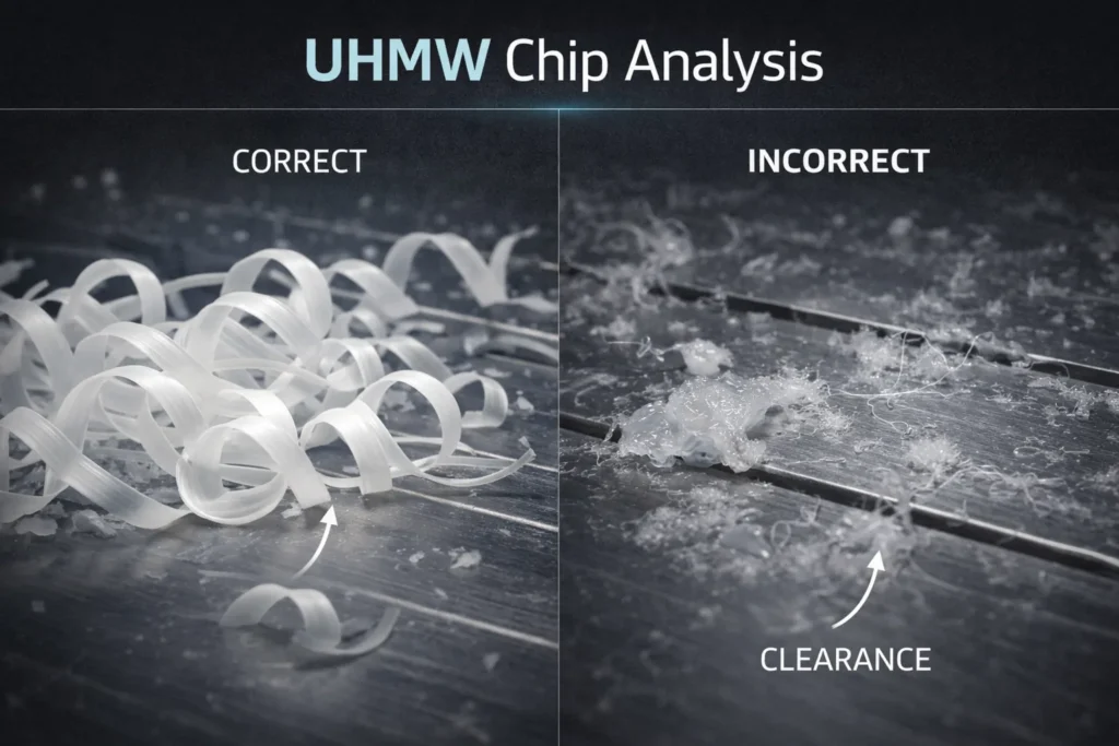
- Chip Type: You want large, “clean” chips. If you see fine dust or “whisps,” your feed is too slow, and you are creating a fire hazard and melting the part.
Chip Load Recommendations
- Milling: Target a chip load of 0.005” – 0.015” per tooth (IPT) for 1/2″ cutters.
- Drilling: Use 0.010” – 0.020” IPR.
- Adjustment: If the tool “chatters,” increase the feed before decreasing the speed. UHMW thrives under high chip loads that stabilize the tool against the material’s elasticity.
Depth of Cut Considerations
- Roughing: Take the heaviest cut your machine rigidity allows (up to 0.250” – 0.500” DOC). Heavy cuts help stabilize the temperature.
- Finishing: Leave at least 0.015” – 0.030” for the final pass. Taking a “whisker” cut (<0.005”) will result in the tool rubbing and the material “pushing away,” leading to dimensional errors.
Preventing Heat Build-Up
- Constant Motion: Never let the tool “dwell” or stop in the cut. If the spindle is turning, the tool must be moving.
- Air Blast: Use high-pressure compressed air to clear chips instantly. Unlike liquid coolant, air ensures chips don’t “re-cut” or wrap around the spindle.
- Sharpness Check: Heat build-up is often the first sign of a dulling edge. If the part feels hot to the touch, change the tool immediately.
Milling UHMW
Understanding Grain Direction and Internal Stress
Extruded UHMW has a linear “grain” similar to wood.
- The Stress: Internal tensions are highest near the surface.
- The Solution: Always mill equal amounts from both sides of a sheet. If you remove 0.100″ from the top but nothing from the bottom, the sheet will “potato-chip” (warp) as the internal stresses rebalance.
Climb vs. Conventional Milling Strategy
- Mandatory: Use Climb Milling.
- Why: Climb milling pulls the tool into the material, creating a “downward” force that stabilizes the part.
- The Risk: Conventional milling “lifts” the material, leading to severe vibration, poor surface finish, and “tearing” at the exit point of the cut.
Roughing vs Finishing Pass Strategy
- Roughing: Leave 0.020″ to 0.040″ of stock. Use high feed rates (0.015″ IPT) to keep the material cool.
- Finishing: Take a clean, continuous pass. Never take a “whisker” cut (<0.005″); the tool will simply rub and deflect, resulting in an out-of-tolerance part with a melted surface.
Avoiding Edge Fuzzing
“Fuzz” occurs when the material is pushed over the edge rather than sheared.
- Tooling: Use a brand-new, single-flute up-cut end mill.
- Technique: Use a sacrificial “backer board” (MDF or scrap plastic) to support the exit edge, preventing the material from tearing as the tool leaves the cut.
Slotting and Pocketing Tips
- Chip Evacuation: Use high-pressure air blast. In a pocket, UHMW chips will “re-weld” to the floor if they aren’t cleared instantly.
- Ramping: Always ramp into the cut at a 3° to 5° angle. Do not plunge straight down (Z-axis), as the material will wrap around the end of the tool and melt the center of the pocket.
Thin-Wall Machining Challenges
- The Limit: Avoid walls thinner than 0.060″.
- The Strategy: Use a “Step-Down” approach rather than full-depth passes. Machine the ID and OD in small vertical increments to maintain the structural integrity of the wall as you descend.
Drilling and Tapping UHMW
Peck Drilling for Chip Evacuation
- Strategy: Use shallow pecks (0.5x to 1x diameter).
- The Risk: UHMW creates long, stringy chips that wrap around the drill. If not cleared, these chips friction-weld to the drill flutes, melting the hole walls.
- Mandatory: Completely retract the drill from the hole on every peck to “fling” the chips off the flutes.
Preventing Hole Deformation
- The Oversize Rule: Always use a drill bit 0.003″ to 0.005″ larger than your target size.
- Elastic Recovery: Because UHMW is elastic, it compresses during the cut and “shrinks back” immediately after the bit is pulled out.
- Coolant: Use flood coolant or air blast inside the hole. If the material feels warm, the hole will be undersized once it cools.
Thread Strength Limitations
- Direct Tapping: UHMW is soft; threads are easily stripped and have poor load-bearing capacity.
- Coarse over Fine: Always use Coarse (UNC) threads. Fine threads (UNF) lack the shear area needed to hold in UHMW and will strip under minimal torque.
- Tapping Tip: Use oversized taps (H5 or H7) to account for the material’s tendency to “close up” on the thread.
Recommended Thread Inserts
If the part requires frequent disassembly or high load, do not rely on raw UHMW threads.
- Stainless Steel Helicoils: Best for permanent high-strength reinforcement.
- Key-Locking Inserts: Best for preventing the insert from backing out due to UHMW’s vibration-dampening properties.
- Avoid: Heat-set inserts. UHMW does not “flow” like ABS or PLA when heated; it simply melts and loses structural integrity. Use mechanically anchored inserts only.
Surface Finish & Deburring
Why UHMW “Fuzzes”
- The Cause: UHMW’s long molecular chains are incredibly elastic. Instead of snapping off cleanly at the tool’s edge, the fibers stretch and tear.
- The Result: A surface that feels “hairy” or velvet-like.
- Pro Tip: Fuzzing is a primary indicator of a dull tool or an insufficient feed rate. If you see fuzz during the cut, increase your feed immediately to force a cleaner shear.
Deburring Tools That Work
Traditional deburring methods often make the problem worse by pulling more fibers out of the material.
- Swivel Blades: Use high-speed steel (HSS) swivel blades specifically ground for plastics.
- Ceramic Blades: Highly Recommended. Ceramic deburring tools stay sharper longer and slice through UHMW fibers without “grabbing” the parent material.
- The “Frozen” Method: For critical deburring, freeze the part at -10°F to 0°F. This temporarily makes the material brittle enough to snap the burrs off cleanly.
Why Sanding Is Ineffective
- Mandatory Warning: Never sand UHMW.
- The Friction Problem: Sanding generates localized heat instantly. Because UHMW has a low melting point, the sandpaper will melt the surface fibers, “smearing” them into the pores of the material.
- The Mess: Sanding creates a permanent “fuzzy” texture that cannot be removed without re-machining the surface.
Achievable Surface Finish Expectations
- Realistic Range: Aim for 32–63 micro-inch (Ra).
- The Finish Myth: You cannot achieve an “optical” or polished finish through machining alone.
- The “Machined Look”: A high-quality UHMW finish will look slightly matte or satin. If the surface looks translucent or “waxy,” it was likely overheated during the final pass.
Tolerances & Dimensional Stability
Stress Relieving: The Secret to High-Precision UHMW
Standard extruded UHMW is packed with internal tension. If you machine one side, the part will warp.
- The Process (Annealing): To hold tolerances tighter than ±.003″, you must rough-machine the part, then “stress relieve” it.
- The Recipe: Heat the part to 250°F (120°C), hold for one hour per inch of thickness, and crucially slow-cool it at a rate of 20°F per hour.
- The Result: This “settles” the molecular chains, allowing for a final finish pass that stays dimensionally stable.
Realistic Machining Tolerances
- Standard Shop Tolerance: ±.005″ to ±.010″ is the industry standard for UHMW.
- Precision Tolerance: ±.002″ is possible but requires a temperature-controlled environment and the annealing process mentioned above.
- The Reality Check: Do not design UHMW parts with ±.0005″ tolerances. The material will move more than that just from the heat of a human hand.
Thermal Expansion Allowances
- The Math: UHMW expands .001″ per inch for every 10°F increase.
- The Shop Floor Trap: If your shop is 90°F and the inspection room is 70°F, a 5-inch part will shrink .010″ by the time it reaches the inspector’s desk.
- Strategy: Always calibrate your calipers/mics to the material temperature, not the air temperature.
Post-Machining Relaxation (Creep)
UHMW is subject to “cold flow” or creep.
- The Failure: A press-fit bushing machined to a perfect interference fit will “relax” over 24–48 hours and eventually become a slip-fit.
- The Fix: Always over-size press-fits by .002″–.004″ to account for this inevitable relaxation.
Slotting & Mounting Design Tips
Because UHMW moves so much with temperature, rigid mounting causes it to buckle or crack.
- Oversized Holes: Use slotted mounting holes rather than fixed bolt holes.
- Shoulder Bolts: Use shoulder bolts that allow the UHMW sheet to “slide” underneath the fastener head as it expands and contracts.
- Floating Fits: Whenever possible, design the part to “float” within a metal track rather than being hard-fastened.
Coolant & Lubrication Recommendations
Air Blast vs Liquid Coolant
- High-Pressure Air Blast: The Preferred Method. Air blast instantly clears long, stringy chips that would otherwise wrap around the tool. It prevents “re-cutting” of chips, which is the #1 cause of surface melting.
- Flood Coolant: Best for Deep Holes/Drilling. Water-soluble oil coolants are effective for deep-cavity work where air cannot reach. However, beware of “chip nesting” in the coolant tank; UHMW chips float and can clog filtration systems.
- Mist Coolant: The Middle Ground. Provides lubrication to reduce friction without the mess of flood coolant.
Avoiding Oil Staining
While UHMW has near-zero moisture absorption (.01%), it can be physically stained or degraded by certain chemicals.
- The Risk: Sulfur-based cutting oils or low-grade mineral oils can leave a permanent yellowish tint or “tacky” residue on the surface.
- The Solution: Use water-based synthetics or vegetable-based mists. If the part is for FDA/Food Grade applications, you must use USP Grade Mineral Oil or dry-cut with air only to maintain compliance.
Managing Heat Without Melting
If you cannot use liquid coolant, you must manage heat through path strategy:
- Tool Engagement: Avoid “buried” cuts. Use trochoidal milling or high-speed machining (HSM) paths that keep the tool in contact with the material for the shortest time possible.
- The 10-Second Rule: If a part feels hot to the touch (above 110°F), stop. Let the material air-cool. Forced cooling (like an ice bath) after the part is already hot will cause uncontrolled shrinking and warping.
- Dwell Time: Set your CAM software to zero dwell time. Any pause in tool motion while the spindle is turning will result in a melted spot.
Common Machining Problems (And How to Fix Them)
| Problem | Root Cause | The Immediate Fix |
| Melting / Galling | RPM too high; Feed too low. | Decrease RPM by 30%; Double your Feed Rate. |
| Part Warping | Unbalanced material removal. | Mill equal amounts from both sides of the sheet. |
| Edge Fuzzing | Dull tool; Conventional milling. | Switch to Climb Milling; Use a Brand New cutter. |
| Undersized Holes | Elastic recovery (shrink back). | Use a drill bit .005″ larger than the target ID. |
| Egg-Shaped ID | Excessive chuck pressure. | Use Soft Jaws or a Wrap-around Collet. |
Melting Instead of Cutting
- The Symptom: Material “gums” onto the tool or leaves a transparent, waxy finish.
- The Fix: Increase Chip Load. You are rubbing the material rather than slicing it. Force the tool to take a larger bite (0.015″ IPR) to ensure the heat leaves the part with the chip. If the tool is turning, it must be moving.
Part Warping After Machining
- The Symptom: Flat sheets “bow” or “potato-chip” after being removed from the fixture.
- The Fix: This is caused by skin tension. Extruded UHMW has higher stress at the surface. You must remove the “skin” from both faces to maintain equilibrium. If you only machine one side, the part will naturally pull toward the un-machined side.
Burr Formation
- The Symptom: “Hairy” edges that are difficult to scrape off.
- The Fix: Use an Up-Cut Spiral O-Flute bit. Burrs usually form when the material is compressed rather than sheared. Ensure your tool has a 30° positive rake. If burrs persist, use a sacrificial backer board to support the material at the exit point.
Tolerance Drift After Installation
- The Symptom: Parts fit perfectly on the bench but seize or loosen after 24 hours.
- The Fix: This is Cold Flow (Creep). UHMW relaxes under mechanical stress. For press-fits, always design with an additional .003″ of interference to account for the material “settling” into its new shape over the first 48 hours.
Hole Shrinkage After Cooling
- The Symptom: A gauge pin fits while the part is on the machine but won’t fit 30 minutes later.
- The Fix: Thermal Contraction. Machining friction expanded the hole while you were cutting it.
- Strategy: Use a Reamer at very low RPM with flood coolant, or intentionally drill the hole .004″–.006″ oversize to allow it to “shrink into” the correct dimension as it reaches room temperature.
Welding and Post-Machining Fabrication
Hot Air Welding
- The Process: Uses a specialized welding gun to feed a UHMW filler rod into a pre-heated joint.
- The Limitation: This produces a bond with only 40–60% of the parent material’s strength.
- Pro Tip: You must scrape the oxidation off the surface immediately before welding. If the material has been exposed to air for more than 24 hours, the weld will fail.
Butt Fusion (Mirror Welding)
- The Gold Standard: This is the most reliable method for joining UHMW sheets or pipes.
- The Technique: Both edges are pressed against a heated “mirror” plate (400°F/204°C) until a melt bead forms, then pressed together under consistent pressure.
- Result: Achieves 90% + joint strength. Avoid overheating; if the material turns brown, the molecular chains have degraded and the joint will be brittle.
Why Adhesives Rarely Work
- Surface Energy: UHMW is a “non-polar” plastic with a surface energy lower than Teflon.
- The Failure: Standard epoxies and cyanoacrylates (super glue) will simply peel off.
- The Exception: Only specialized primers (like 3M DP8005) or plasma/corona surface treatments can create a bond, but these are often more expensive and less reliable than a simple bolt.
Mechanical Fastening Best Practices
- Expansion Gaps: Always drill bolt holes 1/16″ to 1/8″ oversize. As the UHMW expands with temperature, it will buckle or crack if it is pinned tightly.
- Elevated Bolt Heads: Use large OD flat washers to distribute the load. Because UHMW is prone to “cold flow,” a small bolt head will eventually pull through the material under tension.
- Counterbores: When flush mounting, ensure the counterbore depth allows for the bolt head to sit slightly below the surface even if the material expands.
Safety Considerations When Machining UHMW
Chip Management
- The Hazard: UHMW produces continuous, “stringy” chips that do not break. These can wrap around a spinning chuck or spindle at 3,000+ RPM, creating a high-tension “rat’s nest” that can pull tools out of holders or strike the operator.
- The Fix: Never attempt to clear chips by hand while the spindle is turning. Use a long-handled hook or high-pressure air blast to direct the “nest” toward the chip conveyor.
- Housekeeping: UHMW chips are incredibly slippery. A small amount on a shop floor creates a severe slip-and-fall hazard.
Static Buildup
- The Cause: UHMW is an excellent insulator. The friction of the cutting tool generates significant triboelectric charging (static electricity).
- The Effect: Chips will “cling” to the machine windows, sensors, and the operator’s clothing. This static can interfere with CNC touch-probes and sensitive electronic sensors, causing “ghost” alarms or positioning errors.
- The Fix: Use an ionizing air blast or ground the workpiece fixture. If machining dry, an occasional mist of anti-static spray on the material surface can mitigate buildup.
Fire Risk (Fine Shavings)
- The Danger: While bulk UHMW is difficult to ignite, fine shavings and “fuzz” have a high surface-area-to-volume ratio.
- The Ignition Source: A dull drill bit or a rubbing tool can generate enough frictional heat (>580°F/304°C) to ignite the fine dust.
- The Warning: If you see “wispy” or dust-like chips, you are running too slow a feed rate. This dust is a combustible hazard.
- Suppression: Keep a Class A/B fire extinguisher nearby. Do not use water on a plastic fire if it is near electrical CNC components.
When Not to Machine UHMW
High-Temperature Applications
- The Limit: UHMW has a maximum continuous operating temperature of 180°F (82°C).
- The Failure: Beyond this threshold, the material loses its structural rigidity and begins to “slump.” In steam-cleaning environments or near high-friction metal components, UHMW will deform and eventually melt.
- Alternative: Use PTFE (Teflon) or PEEK for high-heat environments.
Tight Tolerance Structural Parts
- The Conflict: UHMW is a “non-rigid” polymer. Its high coefficient of thermal expansion (CTE) makes it impossible to maintain tolerances tighter than ±.002″ in varying environments.
- The Risk: A precision-machined UHMW bracket will expand and contract enough to cause mechanical binding or misalignment in a multi-part assembly.
- Alternative: Use Delrin (Acetal) or G10/FR4 Garolite for dimensionally stable structural components.
Heavy Static Load Components
- The Problem: UHMW is prone to “Cold Flow” (Creep). Under a constant, heavy static load (like a heavy machine base or a highly tensioned bolt), the material will slowly displace and “flow” away from the pressure point.
- The Result: Over time, the part will thin out, bolts will become loose, and the assembly will lose its tension.
- Alternative: Use Nylon 6/6 or Cast Nylon, which offer much higher compressive strength and significantly lower creep rates under load.
Frequently Asked Questions
What is the best tool for cutting UHMW?
A single-flute, high-positive rake, uncoated carbide end mill. Tools designed for aluminum or dedicated “O-flute” plastic cutters are the industry standard. The single-flute design provides the massive chip clearance necessary to prevent “bird-nesting” and frictional heat. Avoid multi-flute tools, as they trap heat and lead to instant material melting.
Does UHMW melt when machined?
Yes, if the friction exceeds 270°F (132°C). Melting occurs when the tool “rubs” the material instead of “slicing” it. This is typically caused by a dull cutting edge, an excessively high RPM, or a feed rate that is too slow. If the chips look like fine hair or dust rather than distinct flakes, the material is likely on the verge of melting.
Can you tap threads in UHMW?
Yes, but use coarse threads and oversized taps. Because UHMW is elastic, it “springs back” after the tap is removed, often resulting in tight or undersized threads. Use an H5 or H7 oversized tap and prioritize UNC (Coarse) over UNF (Fine) threads to prevent stripping. For high-load applications, always use a mechanical thread insert like a Helicoil.
Usama is the founder of PlasticSpec and a materials researcher specialising in engineering thermoplastics. He publishes machining parameters, material property data, and selection guides for Delrin, Nylon, PEEK, PTFE, UHMW, Polycarbonate, and ABS.