Machining Polycarbonate: Precision Techniques, Risks, and Material Decisions
Polycarbonate is a high-impact, ductile thermoplastic favored for its optical clarity and extreme toughness. Successful machining requires precise heat management to prevent melting and proactive stress relief (annealing) to eliminate post-process cracking or dimensional warping.
Is Polycarbonate Suitable for Machining
Machinability Characteristics of Polycarbonate
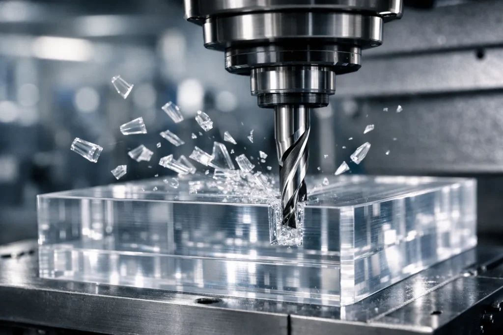
Polycarbonate is highly machinable but behaves differently than brittle plastics. Unlike Acrylic, which chips or cracks under pressure, Polycarbonate is ductile and tends to melt or smear if heat is not managed.
- Extreme Impact Strength: Maintains structural integrity under heavy machining loads.
- High Ductility: Allows for “clean” cuts without breakout at exit points.
- High Elasticity: Requires sharp tools to prevent the material from “pushing” away.
- Low Thermal Conductivity: Heat stays at the tool edge; active cooling is mandatory.
Selecting the Right Grade: Machine Grade vs. Window Grade PC
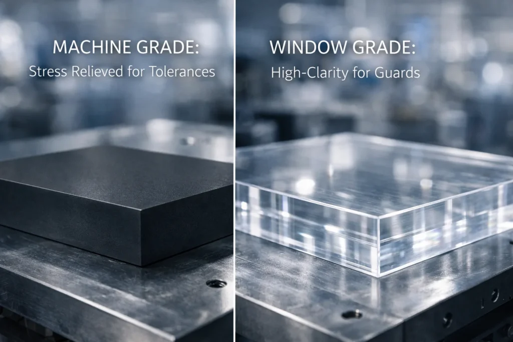
| Feature | Machine Grade (M Grade) | Window Grade (Sign/GP) |
| Appearance | Opaque/Black/Translucent | Optically Clear |
| Internal Stress | Low (Stress Relieved) | High (Extruded) |
| Tolerances | Superior Dimensional Stability | Prone to warping/bowing |
| Best Use | Manifolds, Bushings, Brackets | Guards, Shields, Lenses |
When Machining Polycarbonate Is Not Recommended
Avoid Polycarbonate if your application involves:
- Continuous Friction: PC has poor wear resistance; use Delrin (POM) or PEEK for sliding parts.
- Solvent Exposure: Contact with aromatic hydrocarbons or certain oils causes immediate stress cracking.
- High Heat: Avoid if operating temperatures exceed 120°C (250°F), as the material softens.
Key Challenges When Machining Polycarbonate
Heat Buildup, Melting, and Edge Smearing
Polycarbonate acts as a thermal insulator. Unlike metals, it cannot dissipate heat through the material, causing rapid temperature spikes at the cutting edge. If the temperature exceeds 147°C (297°F), the material reaches its glass transition phase, leading to chip re-welding where melted plastic fuses to the tool flute.
Prevention Strategies:
- High Feed Rates: Ensure the tool moves fast enough to carry heat away in the chip.
- Clearance: Use large-flute tools (1 or 2 flutes) to prevent chip packing.
- Active Cooling: Use clean compressed air or water-based mists to evacuate heat instantly.
Internal Stress, Cracking, and Stress Whitening
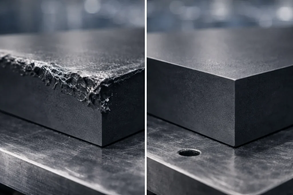
Improper machining causes crazing, a network of fine, microscopic cracks on the surface. This occurs when high localized heat and cutting pressure “stretch” the polymer chains beyond their limit.
- Stress Whitening: Dull tools create friction that “bruises” the plastic, turning it opaque/white.
- Prevention: Use razor-sharp carbide to “shear” the material rather than plowing through it. This minimizes the Heat Affected Zone (HAZ).
Workholding: Preventing Part Deformation and Vibration
Polycarbonate is significantly more flexible than aluminum or steel. Traditional high-pressure clamping will ruin your tolerances.
- Use Soft Jaws: Standard serrated steel jaws will “bite” and create stress risers. Use aluminum or plastic soft jaws to distribute clamping force over a larger surface area.
- Control Clamping Force: Over-tightening causes elastic deformation. The part will measure correctly while clamped but will “spring back” and go out of square once released. Use the minimum force necessary to secure the part.
Tooling and Cutting Parameters for Polycarbonate
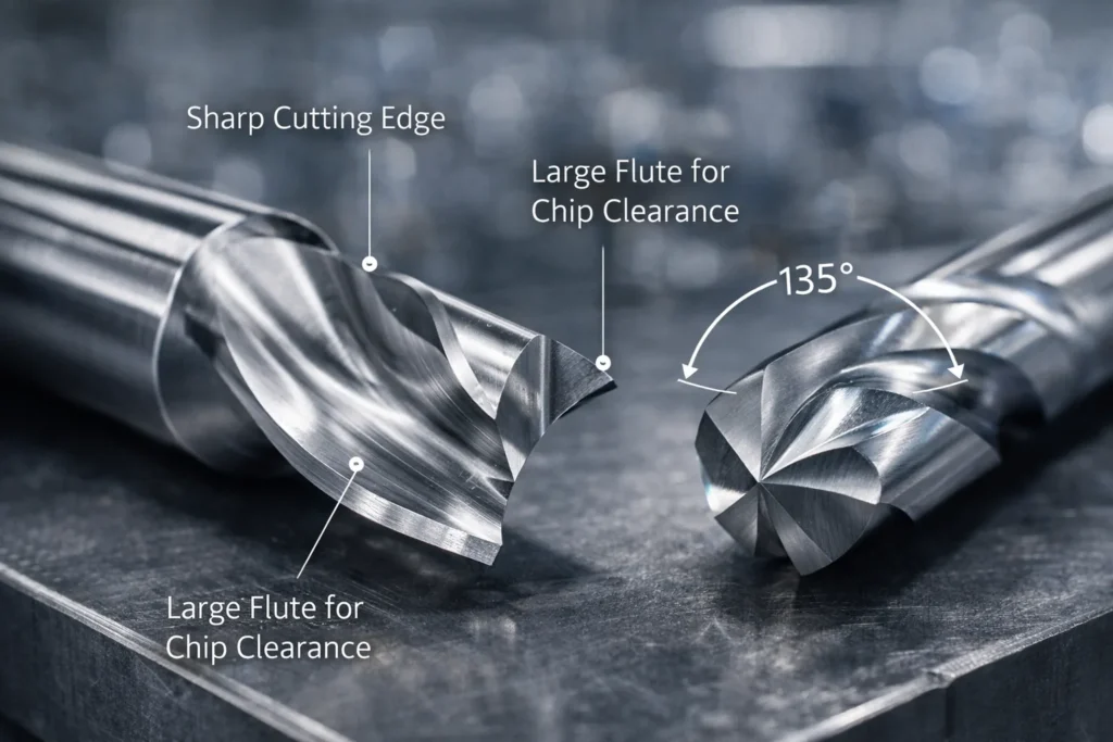
Tool Geometry, Sharpness, and Coatings
Precision in polycarbonate requires razor-sharp edges to shear the material rather than plowing it. Use uncoated carbide or PCD (Polycrystalline Diamond) tools.
- High Rake Angles: Use tools with a positive rake angle (up to 15°) to reduce cutting force and heat.
- Avoid Common Coatings: Do not use TiAlN or AlTiN coatings; their “rounded” edge preparation and high friction coefficients cause rapid heat buildup and melting.
- Flute Count: Stick to 1 or 2 flutes for milling to maximize chip clearance space.
Feeds, Speeds, and Chip Evacuation Control
To prevent melting, you must maintain a high “Feed per Tooth” to ensure the heat is carried away by the chip, not absorbed by the part.
| Parameter | Recommended Range |
| Surface Speed (SFM) | 500 – 1,000 ft/min |
| Chip Load (IPT) | 0.005 – 0.015 inches per tooth |
| Drilling Tip Angle | 135° (prevents “grabbing” upon exit) |
| Spindle Speed (RPM) | Moderate to High (Adjust based on SFM) |
Pro Tip: For drilling, use “Peck Drilling” cycles with short increments (0.5x diameter) to clear chips and prevent heat-soaking the bore.
Coolant Compatibility: Avoiding Chemical Stress Cracking
Polycarbonate is chemically sensitive. Using the wrong lubricant will cause the part to shatter or develop “crazing” cracks hours after machining.
- Safe/Recommended:
- Compressed Air: Best for chip evacuation and cooling.
- Distilled Water: Effective for heat absorption.
- Specialized Plastic Coolants: Water-soluble, sulfur-free, and silicone-free fluids.
- Hazardous (NEVER USE):
- Petroleum-based Oils: Causes immediate structural failure.
- WD-40 / Kerosene: Dissolves the polymer bonds.
- Aromatic Solvents: Benzene, Toluene, or Esters.
Annealing and Stress Relief for Machined Polycarbonate
Pre-Machining vs Post-Machining Annealing
Machining introduces residual internal stresses that lead to dimensional “creep” or delayed cracking (crazing). While Pre-Machined stress-relieved plates (Machine Grade) are easier to cut, Post-Machining annealing is mandatory for high-precision components or parts exposed to chemicals. Post-annealing “relaxes” the polymer chains after material removal, ensuring the part maintains its final dimensions over time.
Temperature Cycles and Cooling Control
Precise thermal control is the only way to eliminate stress without warping the part. Use a programmable oven to follow this High-Value Annealing Schedule:
- Heating Phase: Increase temperature gradually to 120°C (250°F).
- Soak Time: Maintain this temperature for 1 hour per 25mm (1 inch) of cross-sectional thickness. For thin walls (<6mm), a minimum soak of 30 minutes is required.
- Cooling Phase (Critical): Reduce temperature at a rate of 5°C (10°F) per hour until the part reaches room temperature.
Surface Finish and Post-Machining Operations
Achieving Optical-Grade Surface Finish
To restore transparency after machining, follow this strictly sequential process to minimize surface heat:
- Wet Sanding: Start with 400 grit to remove tool marks. Progressively move to 600, 800, 1500, and 2000 grit. Always use water to lubricate and clear debris.
- Mechanical Buffing: Use a clean, soft muslin wheel with a specialty plastic polishing compound (e.g., Novus #2). Keep the part moving to avoid localized frictional melting.
Polishing, Flame Treatment, and Bonding Risks
Method selection determines the long-term structural integrity of the part:
- Vapor Polishing (Best): Uses Weld-On 4 or methylene chloride vapor. High clarity with minimal surface stress.
- Flame Polishing (Risky): Fast but dangerous. It creates high surface tension and internal stress, leading to immediate cracking if the part is not annealed afterward.
- Bonding Warning: Never solvent bond machined polycarbonate without first annealing the part. Residual machining stress + solvent = catastrophic shattering.
Machining Polycarbonate vs Injection Molding
Cost, Lead Time, and Volume Break-Even Points
Selecting the manufacturing process depends on your total part count and speed to market.
- CNC Machining (<500 units): Superior for low-to-mid volumes. No upfront tooling costs ($0) and lead times as short as 3–5 days.
- Injection Molding (>1,000 units): Cost-effective only at high volumes. High initial investment in steel or aluminum molds ($5,000–$20,000+) with 4–8 week lead times.
- Break-Even: The transition point typically occurs between 500 and 800 units, depending on part complexity.
Prototype vs Production Decision Criteria
Design constraints differ significantly between the two methods:
- Wall Thickness: Machining handles thick cross-sections (up to 100mm) without issue. Molding is restricted to thin walls (1.5mm–3.5mm) to prevent sink marks and cooling voids.
- Design Flexibility: Machining allows for undercuts and complex internal geometry without the need for expensive “slides” or “lifters” required in molding.
Polycarbonate vs ABS and Delrin for Machined Parts
Comparison Table: Strength, Impact, and Wear
| Material | Impact Strength | Max Operating Temp | Optical Clarity | Dimensional Stability |
| Polycarbonate (PC) | 10 (Extreme) | 120°C | 10 (Glass-like) | 7 (High stress) |
| Delrin (POM) | 6 (Tough) | 90°C | 0 (Opaque) | 10 (Excellent) |
| ABS | 5 (Rigid) | 80°C | 0 (Opaque) | 8 (Good) |
Selecting the Right Plastic for Load and Environment
Use these engineering decision rules to finalize your material selection:
- Choose Polycarbonate if the application requires unbeatable impact resistance combined with optical transparency or high-temperature stability.
- Choose Delrin (Acetal) for high-precision mechanical parts with sliding friction, as it is self-lubricating and holds tighter tolerances than PC.
- Choose ABS for low-cost, general-purpose structural housings that require impact resistance but do not need transparency or high-heat endurance.
- Choose Nylon for machining: when you need a, tough, abrasion-resistant, and self-lubricating engineering plastic, particularly for parts that must withstand impact or operate without, or with minimal, lubrication.
Typical Applications of Machined Polycarbonate Parts
Transparent Guards, Covers, and Safety Components
Polycarbonate is the industry standard for high-risk visibility areas. It is used extensively for machine tool windows, blast shields, and pressure vessel sight glasses where glass would shatter. Its ability to withstand high-velocity impacts makes it critical for safety enclosures in automated assembly lines.
Industrial, Medical, and Electrical Use Cases
- Medical: Surgical trays and diagnostic equipment (using USP Class VI autoclavable grades).
- Electrical: High-voltage insulators, connectors, and clear cover plates for circuit breakers.
- Fluid Power: High-pressure transparent manifolds for hydraulic testing and flow analysis.
Final Engineering Checklist for Machining Polycarbonate
Design, Process, and Quality Control Questions
Before starting production, verify these 10 critical points to ensure part longevity and dimensional accuracy:
- Radiused Corners: Are all internal corners radiused (min 0.5mm) to eliminate stress risers?
- Grade Check: Is the material Machine Grade for tight tolerances or Window Grade for clarity?
- Tool Sharpness: Are tools factory-new uncoated carbide?
- Coolant Safety: Is the coolant petroleum-free and safe for PC?
- Clamping Force: Is the vise pressure set to the minimum required to avoid bowing?
- Drill Angle: Are all drill bits ground to a 135° tip angle?
- Feed Rate: Is the feed high enough to produce distinct chips, not dust?
- Annealing Plan: Is a post-machining thermal cycle scheduled?
- Stress Inspection: Have parts been checked for crazing under polarized light?
- Handling: Are parts protected from solvent cleaners during final QC?
FAQs
Why does polycarbonate crack after machining?
Polycarbonate cracks (crazes) due to residual internal stress and chemical sensitivity. High cutting heat or improper workholding “stretches” the polymer chains. If the part then contacts incompatible cutting oils or is not annealed at 120°C, the surface tension releases as microscopic or catastrophic cracks.
Can you use WD-40 or standard cutting oil on polycarbonate?
No. You must never use WD-40, kerosene, or petroleum-based oils on polycarbonate. These act as solvents that trigger immediate environmental stress cracking (ESC). Use only compressed air, distilled water, or specialized sulfur-free, water-soluble plastic coolants.
What is the best drill bit angle for polycarbonate?
Use a 135° point angle for drilling polycarbonate. Standard 118° bits tend to “grab” the material upon exit, leading to shattering or pulling the part out of the fixture. High-speed steel (HSS) or uncoated carbide bits with polished flutes are recommended.
How do you prevent polycarbonate from melting during CNC milling?
To prevent melting, maintain a high feed rate (0.005–0.015 IPT) and a moderate spindle speed. This ensures the heat is removed via the chip rather than dwelling in the part. Use single-flute up-spiral end mills to maximize chip evacuation and prevent “gumming.”
Is polycarbonate or acrylic easier to machine?
Polycarbonate is generally easier to machine because it is ductile and does not chip or shatter like acrylic. However, polycarbonate is much more heat-sensitive, requiring stricter control over speeds, feeds, and cooling to avoid melting.