Machining Delrin: Feeds, Speeds, Tooling & Tolerance Guide (2026)
Delrin (Acetal Homopolymer) is the industry standard for high precision plastic machining due to its superior dimensional stability, low friction, and excellent chip formation.
Unlike softer plastics (PTFE or UHMW), Delrin cuts cleanly without “gumming” when managed correctly.
Quick Reference: Machining Snapshot
| Metric | Target Value |
| Optimal SFM | 800 – 1,200 (Roughing) | up to 1,500 (Finishing) |
| Standard Tolerance | ±0.002” (0.05 mm) (Tight: ±0.0005” possible) |
| Critical Temperature | 250°F (121°C) (Thermal expansion begins at 180°F) |
| Best Tooling | Uncoated Polished Carbide (High Rake Geometry) |
Contents
- 1 Why Delrin Machines So Well (Material Behavior Explained)
- 2 Recommended Feeds and Speeds for Machining Delrin
- 3 Best Cutting Tools for Delrin
- 4 Coolant vs Dry Machining: What Works Best?
- 5 Tolerances You Can Achieve with Delrin
- 6 Common Problems When Machining Delrin
- 7 When Machining Delrin Fails
- 8 CNC Machining vs Laser Cutting Delrin
- 9 Delrin vs UHMW in Machining
- 10 When NOT to Machine Delrin
- 11 Alternatives to Delrin for Machining
- 12 Industrial Applications of Machined Delrin Parts
- 13 Final Verdict: Is Delrin the Best Plastic for Machining?
- 14 Frequently Asked Questions
Why Delrin Machines So Well (Material Behavior Explained)
Molecular Structure and Chip Formation
Delrin’s high crystalline density creates a rigid molecular lattice. When a sharp tool edge engages the material, the polymer chains do not stretch or “smear” like HDPE or Nylon. Instead, they reach their shear point quickly and fracture cleanly.
- Result: You get small, discrete chips that are easy to evacuate from deep pockets or blind holes.
- Actionable Insight: Because the material is “free-cutting,” you can use heavier feed rates without sacrificing surface finish.
Low Friction Coefficient and Tool Interaction
Delrin has an exceptionally low coefficient of friction (0.20 – 0.35). It is “self-lubricating,” meaning it slides across the tool’s rake face with minimal resistance.
- Lower Heat: Reduced friction means less thermal energy is transferred into the part.
- Zero Tool Buildup: Material is unlikely to weld to the cutting edge, a common failure in aluminum or softer plastics.
- Tool Longevity: You can often run 10,000+ parts on a single uncoated carbide end mill with negligible wear.
Thermal Expansion Characteristics
This is Delrin’s only significant “weakness” in precision machining. It has a high Coefficient of Linear Thermal Expansion (CLTE) compared to metals.
- The Number: 5.4 x 10⁻⁵ in/in/°F (or 9.7 x 10⁻⁵ m/m/°C).
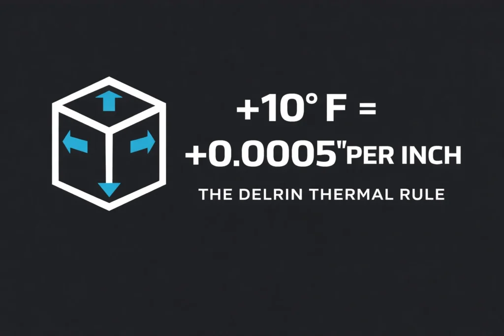
- The Impact: A 1-inch part will grow by 0.0005″ for every 10°F increase in temperature.
- The Solution: For tolerances tighter than ±0.001″, you must allow the part to reach room temperature before taking a final measurement.
Recommended Feeds and Speeds for Machining Delrin
To maximize productivity without melting the workpiece, you must maintain a high chip load. In Delrin, heat is removed through the chip. If your feed rate is too slow, the tool “rubs” rather than “cuts,” leading to thermal deformation and dimensional drift.
CNC Milling Parameters (RPM vs Diameter Table)
The following parameters are optimized for uncoated carbide tooling and a target Surface Feet per Minute (SFM) of 800–1,000.
| Tool Diameter | Spindle Speed (RPM) | Feed Rate (IPM) | Depth of Cut (Roughing) |
| 1/8″ (3.17mm) | 10,000 – 12,000 | 40 – 60 | 0.060″ |
| 1/4″ (6.35mm) | 8,000 – 10,000 | 80 – 120 | 0.125″ |
| 1/2″ (12.7mm) | 5,000 – 7,500 | 150 – 200 | 0.250″ |
| 3/4″ (19.0mm) | 3,000 – 5,000 | 180 – 250 | 0.375″ |
Running these parameters on a live job? If you need Delrin parts machined to these tolerances — without the setup time and material waste — Xometry provides instant online CNC quotes. Upload your CAD file and receive pricing from vetted manufacturers within minutes.
Turning (Lathe) Speed Recommendations
Delrin turns exceptionally well, allowing for heavy depths of cut.
- Surface Speed: Target 800–1,500 SFM.
- Feed Rate: 0.005″–0.015″ IPR for roughing; 0.002″–0.005″ IPR for finishing.
- Key Requirement: Use a large nose radius tool to prevent “grooving” the finish, but ensure it is dead-sharp to prevent part deflection on thin diameters.
Drilling Speed and Peck Strategy
Drilling is the #1 cause of Delrin part failure due to internal heat entrapment.
- Drill Speed: 150–250 SFM.
- Peck Cycle: Mandatory for holes deeper than 2x Diameter.
- Strategy: Use a Full Retract (G83) rather than a high-speed peck (G73) to completely clear chips and allow cool air/fluid to enter the hole.
- Point Angle: 118° is standard, but 135° split point reduces “walking” and exit burrs.
Router vs Industrial CNC Differences
| Feature | Industrial CNC (VMC) | High-Speed Router |
| Spindle Torque | High (Low RPM cutting) | Low (High RPM required) |
| Max RPM | 8k – 15k | 18k – 24k |
| Tooling | 2-3 Flute End Mills | O-Flute (Single Flute) |
| Risk | Over-clamping deformation | Part lifting / Vibration |
Best Cutting Tools for Delrin
Carbide vs HSS
- Carbide (Winner): Solid uncoated micro-grain carbide is the industrial standard. It maintains a sharper edge longer and handles the high surface speeds (1,000+ SFM) required for superior finishes.
- HSS (Niche): High-Speed Steel is only acceptable for manual machining or custom-ground form tools. It dulls faster than carbide, increasing friction and the risk of melting.
- Recommendation: Use Polished Carbide (often labeled for Aluminum) to ensure the lowest possible coefficient of friction.
Single Flute vs Multi-Flute End Mills
- Single Flute (O-Flute): Best for High-Speed Routers (18k+ RPM). It provides maximum “gullet” space for massive chips, preventing heat buildup.
- 2-Flute (Standard): The “Workhorse” for CNC Milling. Balances chip clearance with tool rigidity.
- 4-Flute (Avoid): Never use 4-flute mills for Delrin. The small flutes clog with plastic chips, causing the tool to “weld” to the part within seconds.
Sharp Edge Geometry Requirements
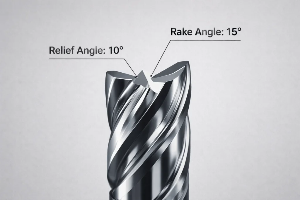
Delrin requires aggressive shearing geometry to prevent “smearing” and edge burrs.
- Rake Angle: High positive rake (15° to 20°) is mandatory.
- Relief Angle: Large primary and secondary relief (10° to 15°) prevents the back of the tool from rubbing against the part.
- Edge Prep: Use Up-sharp edges only. Do not use tools with “honed” or “broken” edges designed for steel.
Tool Coating – Needed or Not?
- Standard Coatings (TiN, TiAlN): Avoid. These coatings are designed for heat resistance in metals but actually dull the cutting edge of the tool at a microscopic level, which increases friction in plastics.
- DLC (Diamond-Like Carbon): Optional/Premium. If you are running high-volume production, DLC coatings provide ultra-low friction and prevent chip welding, but they are rarely necessary for standard Delrin jobs.
- The Rule: Bright/Polished (uncoated) is superior to almost any standard coating for Acetal.
Coolant vs Dry Machining: What Works Best?
When Dry Cutting Is Safe
Dry machining is only recommended for manual operations or light CNC prototyping where precision is secondary to speed of setup.
- Conditions: Shallow cuts (<0.100”), low RPM (<3,000), and short cycle times.
- Risk: Dry cutting allows chips to “re-cut,” which creates friction and a fuzzy surface finish.
- Verdict: Acceptable for roughing, but poor for finishing.
When Air Blast Is Required
High-pressure air blast is the industry-standard “sweet spot” for CNC milling Delrin.
- Why it works: It clears chips instantly from the pocket, preventing “chip packing” and heat re-absorption.
- Benefit: Keeps the workpiece dry for easier cleanup while providing enough convective cooling to maintain ±0.005” tolerances.
- Best for: Deep pocketing, 3D surfacing, and high-speed adaptive clearing.
When Coolant Becomes Necessary
- Tight Tolerances: If your print calls for ±0.001” or better, flood coolant is the only way to keep the part at a constant temperature.
- Deep Hole Drilling: Any hole deeper than 3x Diameter requires coolant to lubricate the flutes and prevent the drill from seizing.
- High SFM: If running at 1,200+ SFM, liquid cooling is required to prevent the tool tip from reaching the 250°F “smear” threshold.
Risks of Overheating and Melting
Exceeding Delrin’s thermal limits results in more than just a scrapped part; it creates an environmental hazard.
- The “Smear” Point: At 250°F (121°C), Delrin loses structural integrity. The tool will begin to “plow” rather than cut, leaving a gummy, raised edge.
- The “Melt” Point: At 347°F (175°C), the material liquifies. It can weld itself to the spindle or tool, potentially causing a machine crash.
- Toxic Outgassing: Overheated Delrin decomposes into Formaldehyde Gas.
- Warning Sign: A sharp, pungent odor.
- Action: Evacuate the area and increase ventilation immediately.
Tolerances You Can Achieve with Delrin
Standard Machining Tolerances
In a climate-controlled CNC environment, the following tolerances are industry standards for Delrin:
| Part Dimension | Standard Tolerance | High-Precision (Tight) |
| Up to 1.000” | ±0.002” (0.050mm) | ±0.0005” (0.012mm) |
| 1.000” – 3.000” | ±0.003” (0.075mm) | ±0.001” (0.025mm) |
| 3.000” – 6.000” | ±0.005” (0.125mm) | ±0.002” (0.050mm) |
Press-Fit Allowances
Delrin’s elasticity makes it ideal for press-fits, but traditional metal-to-metal interference fit tables do not apply.
- Recommended Interference: 0.001″ to 0.003″ total diametrical interference.
- The Limit: Do not exceed 0.005″ interference on small diameters (<0.500″), or the hoop stress may cause the Delrin part to crack or “stress-whiten” over time.
Thermal Expansion Considerations
Thermal expansion is the #1 cause of failed QC reports in Delrin machining.
- The Math: Delrin moves 0.0005” per inch for every 10°F change.
- Critical Threshold: If your shop is 85°F and your inspection room is 68°F, a 4-inch part will shrink by 0.0034” during transport.
- Value-Add Tip: Always document the part temperature at the time of final measurement to resolve disputes with QC.
Dimensional Stability Over Time
Unlike Nylon, Delrin is hydrophobic (it does not absorb significant moisture).
- Moisture Absorption: <0.2% at saturation.
- Stability Benefit: While Nylon parts swell and change size with humidity, Delrin remains dimensionally constant regardless of environmental moisture.
- Post-Machining Warp: If you remove more than 50% of the material from one side of a slab, the internal stresses will cause it to bow. Always machine both sides equally to maintain flatness.
Common Problems When Machining Delrin
Melting Instead of Cutting
- The Symptom: The tool leaves a “raised,” shiny, or bubbly edge rather than a crisp shoulder.
- The Cause: Rubbing. Your feed rate is too slow for your RPM, causing the tool to heat the material to its 250°F (121°C) deformation point.
- The Fix: Increase Feed Rate or Decrease RPM. Aim for a minimum chip load of 0.002″ per tooth to ensure the heat leaves the part inside the chip.
Chip Rewelding
- The Symptom: Small bits of plastic stuck to the finished surface or “welded” into the bottom of a pocket.
- The Cause: Poor Evacuation. Chips are being re-cut by the tool, heating up, and fusing to the workpiece.
- The Fix: Use a High-Pressure Air Blast or Flood Coolant. If milling deep pockets, switch to a Single-Flute End Mill to provide more space for chip clearance.
Dimensional Drift
- The Symptom: The part measures correctly on the machine but is undersized in the inspection room.
- The Cause: Thermal Contraction. The part was measured while “warm” from machining. Delrin shrinks significantly as it cools (5.4 x 10⁻⁵ in/in/°F).
- The Fix: Allow the part to soak at room temperature for 30 minutes before final inspection. Use flood coolant to maintain a constant 68°F (20°C) during the cut.
Tool Gumming
- The Symptom: Plastic “wraps” or “slugs” build up on the tool flutes, leading to tool breakage or poor finish.
- The Cause: Tool Geometry/Coating. Using 4-flute cutters or TiAlN-coated tools designed for steel. The “rough” coating surface causes plastic to stick.
- The Fix: Switch to Uncoated, Polished Carbide tools with a high-rake, “up-sharp” edge.
Warping in Thin Sections
- The Symptom: Large flat plates or thin-walled parts “bow” or “cup” after being released from the vice.
- The Cause: Internal Stress Imbalance. Removing material from only one side of a Delrin slab releases “skin stresses” unevenly.
- The Fix: Symmetrical Machining. Remove equal amounts of material from both side
When Machining Delrin Fails
Delrin is robust, but it has hard physical “breaking points.” Pushing beyond these limits results in immediate part scrap, tool breakage, or dangerous outgassing. Use these specific thresholds to determine if your design is feasible for CNC machining.
| Failure Mode | Critical Limit | Immediate Action |
| Melting | > 250°F Surface Temp | Increase Feed / Decrease RPM |
| Wall Failure | < 0.030″ Thickness | Use custom soft-jaws for support |
| Thread Stripping | < 2x Dia Engagement | Switch to Helicoil or larger thread |
| Gas Release | Sharp Vinegar Smell | E-Stop and Ventilate |
CNC Machining vs Laser Cutting Delrin
Choosing between CNC and Laser cutting for Delrin depends on edge quality and thickness. While Delrin is “laser-safe” (unlike PVC), it is highly flammable. Laser cutting produces a different chemical and physical result than mechanical shearing.
Precision Comparison
- CNC Machining: Holds ±0.001” to ±0.005” consistently. Produces perfectly square edges with zero taper. Ideal for parts requiring tight-tolerance press-fits or bearing seats.
- Laser Cutting: Accuracy is generally ±0.005” to ±0.010”. High-power lasers create a tapered edge (1°–3° kerf angle) as the beam diverges through the material.
- Verdict: Use CNC for 3D geometry and laser for 2D profiles where edge squareness is secondary.
Surface Finish Difference
- CNC Finish: Leaves tool marks (scallops) that can be optimized to 32 Ra. The surface remains the original matte or semi-gloss of the raw stock.
- Laser Finish: The heat “flame-polishes” the edge, often resulting in a glossy, glass-like finish.
- Critical Risk: Laser cutting causes micro-cracking and internal stress at the heat-affected zone (HAZ). This makes laser-cut Delrin prone to stress-cracking if exposed to chemicals or high mechanical loads.
Cost per Part
- Low Volume (1–50 pcs): Laser is 40% cheaper due to zero jig/fixture setup time.
- High Volume (500+ pcs): CNC is more cost-effective for complex parts. While the cycle is slower, the ability to stack sheets or use multi-part fixtures reduces the labor-to-part ratio.
- Thickness Factor: Laser efficiency drops significantly above 0.250” (6mm) thickness; CNC speed remains constant.
Best Use Case for Each
| Feature | CNC Machining | Laser Cutting |
| Best For | Gears, Bushings, Manifolds | Gaskets, Shims, Spacers |
| Max Thickness | Up to 4.0″ (Standard) | < 0.50″ (Practical limit) |
| Edge Quality | Square & Structural | Glossy but Stressed |
| Internal Features | Tapped holes, Pockets | Through-holes only |
Delrin vs UHMW in Machining

While both (UHMW and Delrin) are high-performance engineering plastics, Delrin is for precision; UHMW is for impact. Machinists often mistake them as interchangeable, but their behavior under a cutting tool is diametrically opposed.
Chip Control
- Delrin: Produces short, brittle chips that shatter and evacuate the work zone easily. It is compatible with high-speed automated CNC production.
- UHMW: Produces long, continuous “bird-nests” that wrap around the spindle and tool.
- Actionable Insight: UHMW requires constant manual intervention to clear chips, increasing labor costs by 20-30% compared to Delrin.
Tolerance Stability
- Delrin (The Winner): Boasts a high Flexural Modulus (450,000 psi). It resists deflection and holds ±0.001” consistently.
- UHMW: Extremely “rubbery” with a low modulus (110,000 psi). It deflects away from the tool and “grows” after the cut.
- Comparison: You can reliably machine a Class 2 thread in Delrin; doing so in UHMW is nearly impossible without specialized oversized taps.
Surface Finish
- Delrin: Achieves a 32 Ra finish with standard carbide tooling. It maintains sharp, crisp edges and corners.
- UHMW: Leaves a “fuzzy” or fibrous finish because the material tears rather than shears. It is prone to heavy burring that requires manual deburring with a torch or blade.
Wear Resistance
- UHMW (The Winner): Offers superior abrasion resistance and impact strength. It is the better choice for liners, chutes, and high-impact bumpers.
- Delrin: Superior for mechanical wear (gears/bushings) where dimensional integrity and low friction under load are required.
When NOT to Machine Delrin
Quick Check: Is Delrin the Wrong Choice?
| Requirement | Delrin Capability | Better Alternative |
| Heat > 250°F | Failure (Melts) | PEEK or PTFE |
| High Acid Resistance | Poor (Corrodes) | PVDF or Polypropylene |
| Zero Moisture Absorption | Good (0.2%) | UHMW (0.0%) |
| Structural Transparency | Zero (Opaque) | Polycarbonate (PC) |
| High Impact Strength | Moderate | Nylon 6/6 |
Actionable Insight: If your part requires flame retardancy (UL 94 V-0), do not use Delrin. It is highly flammable and difficult to extinguish once ignited. Switch to Ultem (PEI) for these applications.
Alternatives to Delrin for Machining
Quick Comparison Table
| Material | Machinability | Max Temp | Key Strength |
| Delrin | 10 / 10 | 180°F | Precision & Stability |
| Nylon | 7 / 10 | 210°F | Impact & Toughness |
| PTFE | 8 / 10 | 500°F | Chemical Inertia |
| PEEK | 9 / 10 | 480°F | High-Load / High-Heat |
Nylon
- The Difference: Nylon (PA 6/6) is tougher and has higher impact resistance than Delrin.
- Machining Behavior of Nylon: More difficult. Nylon is hygroscopic (absorbs moisture), causing it to swell during machining. It produces longer, “stringier” chips.
- Best For: Applications requiring high impact strength or parts exposed to heavy vibration where Delrin might crack.
- Warning: Do not use Nylon for high-tolerance parts (>±0.002″) due to moisture-induced dimensional shift.
UHMW
- The Difference: Virtually zero friction and zero moisture absorption.
- Machining UHMW: Poor. It is soft and “rubbery.” It deflects away from the tool and requires specialized sharp wood-style bits to prevent “fuzzing.”
- Best For: High-wear liners, chutes, and impact bumpers where precision is secondary to durability.
PTFE
- The Difference: Exceptional chemical resistance and a service temperature of 500°F (260°C).
- Machining Behavior: Easy but unstable. PTFE is very soft and “creeps” under the pressure of a CNC vice. It is difficult to hold tolerances tighter than ±0.005″.
- Best For: High-heat seals, gaskets, and chemical manifolds where Delrin would dissolve or melt.
PEEK (for high performance)
- The Difference: The “Gold Standard” of engineering plastics. It maintains its strength up to 480°F (250°C) and is chemically inert.
- Machining Behavior: Excellent. PEEK machines similarly to Delrin (brittle, clean chips) but is much harder on tooling. Carbide is mandatory.
- Best For: Medical implants, aerospace components, and oil/gas parts that exceed Delrin’s physical limits.
- Cost Factor: PEEK is roughly 10x to 20x more expensive than Delrin.
Industrial Applications of Machined Delrin Parts
Precision Mechanical Components
- Gears and Pinions: Delrin is the gold standard for high-speed, low-torque gears. Its self-lubricating properties eliminate the need for grease, making it ideal for clean-room environments.
- Bearings and Bushings: Used where low-friction rotation is required under moderate loads. It outlasts Nylon in high-moisture environments because it does not swell.
- Rollers and Guides: Machined Delrin rollers provide quiet, non-marring operation in conveyor systems and specialized material handling equipment.
Medical and Life Sciences
- Surgical Instruments: Used for handles and trial implants because it is stiff and maintains tight tolerances. Note: Delrin 150 is typically used for its FDA compliance.
- Fluid Manifolds: Because it does not absorb chemicals or water, Delrin is preferred for complex manifolds in diagnostic equipment where channel integrity is critical.
Electrical and Automotive
- Electrical Insulators: Delrin has high dielectric strength, making it a safe housing for electrical connectors and terminal blocks.
- Fuel System Parts: It is highly resistant to hydrocarbons and ethanol, frequently used in fuel sender units and cap assemblies.
- Fasteners and Washers: Machined Delrin screws and spacers provide high-strength clamping without the risk of corrosion or electrical conductivity.
Final Verdict: Is Delrin the Best Plastic for Machining?
Yes. For 90% of engineering applications, Delrin is the undisputed “Gold Standard” for CNC plastic machining. No other polymer offers the same combination of metal-like chip formation, high dimensional stability, and low tool wear.
However, “best” is relative to your specific environmental constraints. Use the decision logic below to finalize your material selection.
The Decision Matrix: Choose Delrin If…
- Precision is Non-Negotiable: You need to hold ±0.001” (0.025mm) or tighter.
- High-Cycle Mechanical Movement: You are machining gears, cams, or sliding bushings.
- Wet Environments: Your part will be submerged or exposed to high humidity (Delrin won’t swell like Nylon).
- Automated Production: You need to run “lights-out” CNC cycles where chip management is critical.
Avoid Delrin If…
- Continuous Heat Exceeds 180°F: The part will soften and lose its “press-fit” or structural integrity.
- Strong Acids are Present: Delrin will become brittle and crack (Use Polypropylene or PVDF instead).
- Flame Retardancy is Required: Delrin is highly flammable (Use Ultem or FR-ABS).
- High Impact Loads: Heavy shock or “hammering” may cause Delrin to shatter (Use Nylon 6/6 or UHMW).
Frequently Asked Questions
Does Delrin melt during machining?
Yes, Delrin melts at 347°F (175°C), but structural smearing begins at 250°F (121°C). Melting typically occurs when the feed rate is too low or the tool is dull, causing “rubbing” friction rather than cutting.
Can you machine Delrin without coolant?
Yes, Delrin can be machined dry, but high-pressure air blast is highly recommended. While Delrin is self-lubricating, air blast is critical for chip evacuation in pockets and holes. For tolerances tighter than ±0.001”, flood coolant is mandatory to prevent part “growth” caused by thermal expansion during the machining cycle.
What tolerance can Delrin hold?
Standard CNC machining can hold ±0.002” (0.05mm), while high-precision setups can achieve ±0.0005” (0.012mm). Delrin is the most dimensionally stable engineering plastic, but its high Coefficient of Thermal Expansion means you must measure parts at a stabilized room temperature (68°F/20°C) to ensure accuracy across a production run.
Is Delrin better than Nylon for CNC machining?
Yes, Delrin is superior to Nylon for CNC machining in terms of precision and chip control. Delrin produces short, brittle chips that evacuate easily, whereas Nylon produces long, stringy nests that clog spindles. Additionally, Delrin does not absorb moisture, making it much more dimensionally stable than Nylon in humid environments.
What RPM is too high for Delrin?
Any RPM above 15,000 is “too high” if the feed rate is not increased proportionally to prevent rubbing. In industrial CNC milling, 5,000–10,000 RPM is the standard “sweet spot.” If using a high-speed router at 20,000+ RPM, you must use a single-flute O-flute tool and a very high travel speed (200+ IPM) to avoid melting the material onto the bit.
Usama is the founder of PlasticSpec and a materials researcher specialising in engineering thermoplastics. He publishes machining parameters, material property data, and selection guides for Delrin, Nylon, PEEK, PTFE, UHMW, Polycarbonate, and ABS.