
Machining Delrin: Feeds, Speeds, Tolerances and Fixes
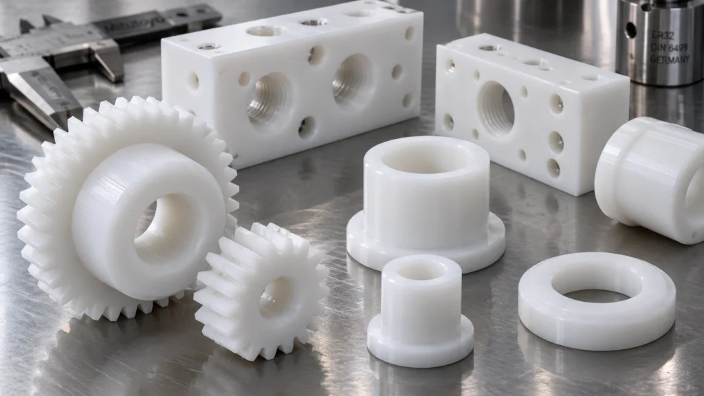
Delrin (POM-H acetal) machines on standard equipment with few special requirements [6].
What goes wrong is not the cutting. It is heat, clamping, stress release and thermal growth.
This guide gives published speed and feed ranges, worked examples, tool geometry, tolerance and thermal growth numbers, stock and porosity checks, and an ordering checklist, with the source named for every range.
Quick answer
- Starting ranges for acetal homopolymer: milling 920 to 1,640 ft/min; turning 980 to 1,960 ft/min at 0.004 to 0.015 in/rev; drilling 165 to 650 ft/min at 0.004 to 0.012 in/rev with peck cycles; sawing 1,640 to 2,600 ft/min [1] [2] [3] [21].
- Tolerance: one service publishes ±0.005 in as standard and ±0.002 in for precision work. Thermal growth is 0.00068 in per inch per 10 °F [9] [10] [13].
- Check first: centerline porosity in thick stock, and heat and fumes if chips smoke or discolor.
Where to start
- Machinist: Speeds and Feeds, then Troubleshooting.
- Designer: Tolerance and Thermal Growth, then Design Rules.
- Buyer or QA: Stock Form and Porosity, then Ordering Machined Delrin Parts.
- Part out of tolerance: go to Tolerance and Thermal Growth first, then Troubleshooting.
Speeds and Feeds
Published starting ranges
| Operation | Surface speed | Feed | Source |
| Milling | 920 to 1,640 ft/min (280 to 500 m/min) | Up to 0.55 mm (0.022 in) per tooth | Curbell milling table [2] |
| Turning | 980 to 1,960 ft/min (300 to 600 m/min) | 0.004 to 0.015 in/rev; rough 0.015, finish 0.005 or less | Curbell turning table [1] |
| Drilling | 165 to 650 ft/min (50 to 200 m/min) | 0.004 to 0.012 in/rev | Curbell drilling table [3] |
| Drilling a 1 in hole (insert drill) | 500 to 800 rpm | 0.005 to 0.015 in/rev | Boedeker [4] |
| Sawing | 1,640 to 2,600 ft/min (500 to 790 m/min) | Tooth pitch 0.078 to 0.197 in | Curbell sawing table [21] |
Curbell’s tables list acetal homopolymer and copolymer with identical values. These are published starting ranges, not a guarantee for your machine, tool or stock.
The sources agree on the principle even where numbers differ.
Emco says slow feed/fast speed and slow speed/fast feed both machine well.
DuPont says cutting speed is the critical factor to watch.
The Cambridge design cookbook says a high speed and coarse feed throws chips away and prevents the rubbing that dulls the tool [6] [7] [8].
In practice, avoid slow feeds at high rpm: rubbing makes heat, and the chip should carry it away.
Spindle speed for the published range
RPM = surface speed (ft/min) × 3.82 ÷ tool diameter (in). For the milling range of 920 to 1,640 ft/min:
| Cutter diameter | RPM at 920 ft/min | RPM at 1,640 ft/min |
| 1/4 in | 14,060 | 25,060 |
| 1/2 in | 7,030 | 12,530 |
| 3/4 in | 4,690 | 8,350 |
| 1 in | 3,510 | 6,260 |
This is our arithmetic. Small cutters often cannot reach these speeds on a standard spindle.
Engineering note: run the spindle’s maximum and keep feed per tooth up, rather than slowing the feed to compensate.
Worked examples
These apply the published ranges. They are arithmetic, not recommendations for your setup.
| Job | Calculation | Result |
| Milling with a 1/2 in, 2-flute cutter at the bottom of the range (920 ft/min), 0.003 in per tooth | RPM = 920 × 3.82 ÷ 0.5; feed = 0.003 × 2 × 7,030 | About 7,030 rpm and 42 in/min. Chip load is well under the 0.022 in/tooth published maximum |
| Finish turning a 1 in diameter at 1,000 ft/min, 0.005 in/rev | RPM = 1,000 × 3.82 ÷ 1; feed = 3,820 × 0.005 | About 3,820 rpm and 19 in/min. Speed and feed are inside the published turning ranges |
| Drilling with a 1/4 in drill at 300 ft/min, 0.006 in/rev | RPM = 300 × 3.82 ÷ 0.25; feed = 4,580 × 0.006 | About 4,580 rpm and 27 in/min. Peck so depth never exceeds 0.75 to 1.0 in (3 to 4 diameters) before withdrawal [3] |
One machinist reports that 0.003 in per flute is easy on Delrin and that a 1/2 in cutter at 6,000 rpm (about 800 ft/min) gave clean parts. That is a single anecdote [20].
Tool Geometry, Coolant and Work holding
Tool geometry
| Operation | Published geometry | Source |
| Milling | 2 to 4 flutes, with fewer flutes giving better chip evacuation; 30 to 45° helix; positive rake 0 to 10°; relief 10 to 15° | Boedeker [5] |
| Turning | Fine C-2 carbide inserts; polished top surface; relief 6 to 8°; rake 0 to 5°; side angle 45 to 60° | Curbell [1] |
| Drilling | 90 to 118° point angle with 9 to 15° lip angle; support the back side; reduce feed near exit; peck so depth never exceeds 3 to 4 diameters before withdrawal | Curbell [3] |
| Sawing | Clearance 20 to 30°, rake 0 to 5° | Curbell [21] |
Carbide or HSS
Curbell says HSS tooling works well for most thermoplastics and carbide is recommended for reinforced materials, while recommending carbide inserts for turning.
Polished surfaces reduce material build up [1] [2].
Single flute or more
Sources differ. Emco recommends single-flute mills for lower friction heat and more chip clearance, Boedeker lists 2 to 4 flutes, and Curbell finishes with 2 or 4 flutes depending on chip behavior [2] [5] [6].
Start with 1 or 2 flutes in pockets and deep slots, and test.
Coolant
Boedeker says coolants are generally not required except for drilling and parting off.
Emco says oils or water are typically unnecessary but may help at very high speeds, and recommends coolant when drilling at high rates [4] [6].
Work holding
Curbell warns that clamping needs care to avoid deforming or springing the stock [2].
Boedeker notes that plastics are much more elastic than metals [4], and Fictiv advises clamping thin parts down with fasteners [12]. Use light, distributed clamping and support thin sections.
Sawing
Curbell recommends relatively thin blades for thick-walled parts to avoid frictional heat, and well-sharpened, strongly offset blades [21].
Boedeker lists carbide-tipped, triple-chip blades with a low positive hook of 5 to 10°, 4 to 10 teeth per inch depending on thickness, and lower speeds to prevent melting [22].
- Speed and pitch: 1,640 to 2,600 ft/min, with tooth pitch 0.078 to 0.197 in (about 5 to 13 teeth per inch, our conversion)[21].
- If the cut edge melts: feed faster or slow the blade speed, and watch for dulling teeth [23].
- Start with relieved stock: residual stress in plastic is the enemy during sawing [23].
Heat Limits and Fumes
Temperature limits
On the Plastics International Delrin 150 sheet, long-term service is 185 °F, heat deflection at 264 psi is 257 °F, and melting is 347 °F [13].
We found no published “smear temperature.” Treat the 264 psi heat deflection figure as the point where a loaded or clamped part loses stiffness.
Fumes and exposure
An acetal safety data sheet reports heavy formaldehyde fuming above 230 °C (446 °F) [18].
OSHA’s formaldehyde limits are 0.75 ppm (8-hour average) and 2 ppm (15-minute short-term) [19].
If chips smoke or discolor, stop, fix the cause and ventilate. Do not use smell as your monitor.
Tolerance and Thermal Growth
Published tolerances
| Published figure | Value |
| Standard CNC machining tolerance (Protolabs) | ±0.005 in [10] |
| Precision or production machining tolerance (Protolabs) | ±0.002 in [9] |
| Thermal expansion, Delrin 150 | 6.8 × 10⁻⁵ in/in/°F |
| Water absorption, Delrin 150 | 0.25 % (24 h), 0.9 % (saturation) |
Delrin 150 values are from the Plastics International data sheet [13].
Boedeker notes that the relative softness of plastics makes tight tolerances harder to hold during and after machining [4].
Thermal growth
| Feature length | Growth per 10 °F swing |
| 1 in | 0.0007 in |
| 3 in | 0.0020 in |
| 6 in | 0.0041 in |
This is our arithmetic from 6.8 × 10⁻⁵ in/in/°F. A 4 in part measured at 85 °F and again at 68 °F (a 17 °F difference) changes by 0.0046 in.
What this means. A 10 °F swing moves a 3 in feature by 0.0020 in, as much as a ±0.002 in tolerance on that dimension.
State the inspection temperature on the drawing, and let the part reach it before you measure. For tight fits in wet service, ask for dimensions after moisture conditioning, since saturation uptake is 0.9%.
Stress, annealing and moisture
DuPont says most stock shapes are pre-annealed, and that for high tolerance parts an annealing step may be necessary before light finish machining.
Fictiv notes Delrin is highly susceptible to warping on large flat parts or thin walls [7] [12].
Need a tolerance held on a specific feature? Upload your STEP, IGES or DXF file for a tolerance check and quote
Machining Delrin Components for a Current Project?
Skip the shop-floor trial and error. Upload your STEP, IGES, or DXF files for an instant manufacturability review, tight-tolerance verification, and fast production quotation.
Request a Precision Machining Quote →🔒 NDA Compliant • 1 to 10,000+ Production Parts • Fast Turnaround
Stock Form and Porosity
Stock sizes and listings
Delrin 150 NC010 shapes are listed in rod from 0.187 to 10.00 in diameter and plate from 0.031 to 5.00 in thick, with ASTM D6100 and FDA 21 CFR 177.2480 listings on the natural grade [14].
Centerline porosity
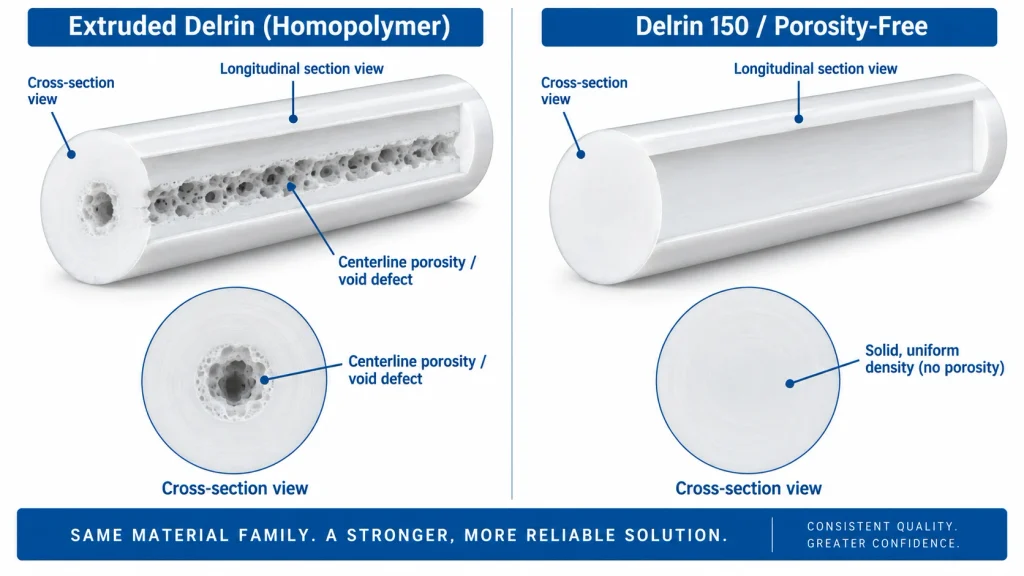
The same data sheet warns of a low-density center, especially in large cross-sections [14].
Boedeker describes it as interconnected micro-porosity of about 100 to 150 microns in homopolymer stock, and one distributor says 150 is not USP Class VI compliant because of it.
Copolymer (POM-C) stock is reported to have little or no centerline porosity [15] [16] [17].
Rule of thumb: if a bore, seal face or fluid passage runs through the center of thick Delrin stock, get a porosity statement from the supplier first, or compare POM-C.
Design Rules for Machined Delrin
Walls
Protolabs lists 0.020 in as the practical minimum turned wall.
Xometry advises against going below 0.060 to 0.080 in for acetal because thin walls are hard to fixture and can flex, warp or chatter.
Fictiv advises avoiding thin walls, or clamping the part down with fasteners [10] [11] [12].
Inside corners
The cutter radiuses sharp inside corners, and Curbell recommends rounded corners in pockets. One machinist notes acetal can chip on sharp corners [2] [10] [20].
Cost levers
Acetal is one of the more expensive plastics, and Fictiv advises limiting setups, inspection dimensions, tight tolerances, and deep pockets with small radii [11] [12].
Tolerance only the features that need it.
Threading, Tapping and Finishing
We found no authoritative published tap-drill, thread-engagement or deburring table for acetal.
One machinist reports rarely having problems drilling or tapping Delrin, notes the material can push away instead of cutting a chip, and suggests single-flute cutters [24].
Prove threads and edges on a coupon before committing, and check thread engagement and fit on the real part.
Troubleshooting
| Symptom | Likely cause | First fix |
| Gummy, shiny or bubbly edge; build-up on the tool | Rubbing and heat | Replace or sharpen the tool, use polished surfaces and generous relief, and raise feed per tooth so the chip carries the heat [1] [8] |
| Chipping at corners or hole exit | Unsupported exit, sharp corners | Support the back side, reduce feed near exit, round inside corners [2] [3] |
| Right on the machine, wrong in QA | Thermal growth or moisture | Agree the measurement temperature and use the growth table above [13] |
| Bowing or cupping after release | Stress release in thin or large flat sections | Use annealed stock for tight work, avoid thin walls or fasten the part down, and balance material removal on both faces where the part allows (shop practice, no published rule found) [7] [12] |
| Size changes after unclamping | Elastic plastic under clamp load | Reduce clamping force and support the part[2] |
| Melted edge when sawing | Too much heat at the blade | Feed faster or slow the blade speed, and check tooth sharpness [23] |
| Leak through a machined bore or face | Centerline porosity | Get a porosity statement, or compare POM-C [14] [16] |
| Chips smoking or discolored | Overheating | Stop and ventilate; see Fumes and Exposure [18] |
Ordering Machined Delrin Parts
- Material and form: Delrin 150 NC010 extruded shape per ASTM D6100, or POM-C if the part is porosity sensitive.
- Porosity statement for the diameter or thickness if a bore, seal face or fluid path crosses the center.
- Critical features marked individually, with tolerance on each. The published default is ±0.005 in.
- Inspection temperature stated on the drawing.
- Annealing requirement for tight tolerance or thin parts.
- Certificates: match FDA or NSF statements to the exact form and color you are buying.
Machining Delrin Components for a Current Project?
Skip the shop-floor trial and error. Upload your STEP, IGES, or DXF files for an instant manufacturability review, tight-tolerance verification, and fast production quotation.
Request a Precision Machining Quote →🔒 NDA Compliant • 1 to 10,000+ Production Parts • Fast Turnaround
Is Machining the Right Route for your project?
| Your situation | Read next |
| Thin flat profile, many pieces, no tight fits | Laser Cut Delrin |
| High volume, molded geometry | Delrin 100 vs. 150 |
| Prototype or non-critical shape | Delrin 3D Printing |
| Strong acid or bleach exposure | HDPE vs. Delrin |
| Hot water, steam or chlorine | Delrin vs. Acetal |
| Wet, abrasive wear | UHMW vs. Delrin |
| More toughness needed | Delrin vs. Nylon |
FAQ
Does Delrin melt during machining?
Can you machine Delrin without coolant?
What tolerance can machined Delrin hold?
Do I need to anneal Delrin before machining?
Most stock shapes are pre-annealed, and DuPont says annealing may be necessary before light finish machining on high tolerance parts.
Why did my part change size after machining?
Thermal growth (6.8 × 10⁻⁵ in/in/°F), moisture uptake and stress release are the usual causes. Use the tables above to find which one explains your error.
Related Guides
- Delrin (Acetal Homopolymer): Properties, Grades and Applications
- Laser Cut Delrin: Is It Safe, and What Settings Work?
- Delrin 3D Printing:Challenges, Print Settings and Best Alternatives
- Delrin 100 vs 150: Which Grade for Machining and Molding?
- Delrin vs. Acetal: Are They Even Different Materials?
- Delrin vs. Nylon: Which Engineering Plastic Should You Choose?
- Delrin vs. ABS: Strength, Machining, Cost & Selection
Sources
All sources last checked October 9, 2026. Ranges and typical values are published guidance, not guarantees for your machine, tool or stock.
- https://www.curbellplastics.com/services-capabilities/fabrication-machined-parts/plastic-machining-guidelines/plastic-turning-machining-guidelines/
- https://www.curbellplastics.com/services-capabilities/fabrication-machined-parts/plastic-machining-guidelines/plastic-milling-machining-guidelines/
- https://www.curbellplastics.com/services-capabilities/fabrication-machined-parts/plastic-machining-guidelines/plastic-drilling-machining-guidelines/
- https://boedeker.com/Technical-Resources/Technical-Library/Plastic-Machining-Guidelines
- https://www.boedeker.com/Technical-Resources/Plastic-Machining-Guidelines/Plastic-Milling-Machining-Guidelines
- https://www.emcoplastics.com/delrin-machining-and-fabrication/
- https://www.plasticsintl.com/media/xgmka1p3/machining_glass_reinforced_resins.pdf
- https://wwwmdp.eng.cam.ac.uk/web/library/enginfo/cookbook/manufacturing/plastics/machining.html
- https://www.protolabs.com/de-de/ressourcen/design-tipps/bessere-cnc-teile-durch-feinabstimmung-der-toleranzen/
- https://www.protolabs.com/services/cnc-machining/cnc-turning/design-guidelines/
- https://www.xometry.com/material-cnc-machining-plastic-delrin
- https://www.blog.fictiv.com/materials/cnc-machining-delrin
- https://www.plasticsintl.com/media/05oith4t/delrin-150-data-sheet.pdf
- https://plastics.tridentplastics.com/Asset/TDS_Delrin150%20NC010.pdf
- https://www.boedeker.com/Portals/0/Documents/Acetals-Understanding-the-Differences-POMC-POMH-Boedeker-Technical-Guide-Acetals-New-Logo.pdf
- https://professionalplastics.com/Acetal-Delrin
- https://sterlingplasticsinc.com/product/delrin-150-homo-polymer/
- https://www.mcam.com/mam/29867/MCAM-ACETRON-POM-H-AF-EN-SDS-1000-220818.pdf
- https://ehs.prod.fbweb.psu.edu/sites/ehs/files/formaldehyde_-_osha_fact_sheet.pdf
- https://forums.autodesk.com/t5/fusion-manufacture-forum/mill-cutting-delrin-speeds-and-feeds-anyone/m-p/6350924/highlight/true
- https://www.curbellplastics.com/services-capabilities/fabrication-machined-parts/plastic-machining-guidelines/plastic-sawing-machining-guidelines/
- https://www.boedeker.com/Technical-Resources/Plastic-Machining-Guidelines/Plastic-Sawing-Machining-Guidelines
- https://modernplastics.com/?p=2370
- https://www.emastercam.com/forums/topic/99237-drilling-tapping-pvc-and-acetal/
Last Reviewed: October 2026

Usama Ayub is the founder of PlasticSpec and a polymer manufacturing engineer with eight years of hands-on industrial experience in PET, PA6, and PA66 fiber and filament yarn production. He writes material property and selection guides for Delrin, Nylon, PEEK, PTFE, UHMW, Polycarbonate, and ABS.